


August 1990 8
Philips Semiconductors Product specification
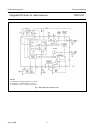
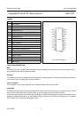
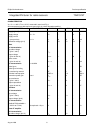
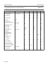
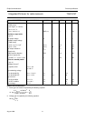
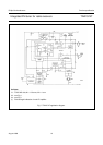
Integrated FM tuner for radio receivers TDA1574T
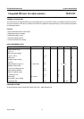
Notes to the characteristics
1. Power gain conversion is equated by the following equation:
2. Voltage gain is equated by the following equation:
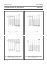
Wideband threshold
(RMS value)
(see Figs 3, 4, 5 and 6)
at V
14
= 0.7 V;
V
20
= V
P
/2; I
20
= 0 EMF
2(rms)
− 17 − mV
Oscillator output buffer
(pin 9)
DC output voltage V
9
− 6 − V
Oscillator output voltage
(RMS value)
at R
L
= oo; C
L
= 2 pF V
9(rms)
− 110 − mV
at R
L
= 75 Ω V
9(rms)
30 50 − mV
DC output resistance R
9-17
− 2.5 − kΩ
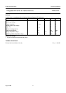
Signal purity
Total harmonic distortion THD −−15 − dB
Spurious frequencies
at EMF 1 = 1 V; R
S1
= 50 Ω f
S
−−35 − dB
Electronic standby switch
(pin 11)
Oscillator; linear IF
amplifier; AGC T
amb
= −40
to + 85 °C
Input switching voltage
for threshold ON V
20
= > V
P
−3 V V
13
0 − 2.3 V
for threshold OFF V
20
= < 0.5 V V
13
3.3 − 23 V
Input current
at ON condition V
13
= 0 V −I
13
−−150 µA
at OFF condition V
13
= 23 V −I
13
−−10 µA
Input voltage I
13
= 0 V
13
−−4.4 V
PARAMETER CONDITIONS SYMBOL MIN. TYP. MAX. UNIT
10
4V
M out()
10.7MHz()
2
EMF1 98 MHz()
2
-----------------------------------------------------------
x
R
S1
R
ML
-----------
log
20
V
12
V
16 15–
------------------log