


August 1990 6
Philips Semiconductors Product specification
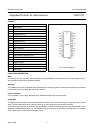
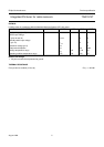
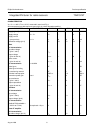
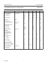
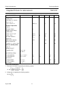
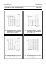
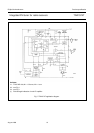
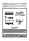
Integrated FM tuner for radio receivers TDA1574T
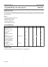
CHARACTERISTICS
V
P
= V
17-4
= 8.5 V; T
amb
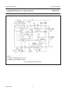
= 25 °C; measured in test circuit Fig.1;
All measurements are with respect to ground (pin 4); unless otherwise specified
PARAMETER CONDITIONS SYMBOL MIN. TYP. MAX. UNIT
Supply (pin 17)
Supply voltage V
P
= V
17
V
17
7 − 14 V
Supply current
(except mixer) I
P
= I
17
I
17
16 23 30 mA
Reference voltage (pin 5) V
5
4.0 4.2 4.4 V
Mixer
DC characteristics
Input bias voltage
(pins 1 and 2) V
1,2
− 1 − V
Output voltage
(pins 18 and 19) V
18,19
4 − 35 V
Other current
(pins 18 and 19) I
18 + 19
− 4.5 − mA
AC characteristics
f
i
= 98 MHz
Noise figure NF − 9 − dB
Noise figure including
transforming network NF − 11 − dB
3rd order intercept point EMF1
IP3
− 115 − dB/µV
Conversion power gain note 1 G
CP
− 14 − dB
Input resistance
(pins 1 and 2) R
1,2
− 14 −Ω
Output capacitance
(pins 18 and 19) C
18, 19
− 13 − pF
Oscillator
DC characteristics
Input voltage
(pins 7 and 8) V
7,8
− 1.3 − V
Output voltage (pin 6) V
6
− 2 − V
AC characteristics
Residual FM (bandwidth =
300 Hz to 15 kHz) de-emphasis = 50 µs ∆f − 2.2 − Hz
Linear IF amplifier
DC characteristics
Input bias voltage (pin 15) V
15
− 1.2 − V