


July 1994 6
Philips Semiconductors Product specification
2 x 22 W stereo BTL differential amplifier
with speaker protection and dynamic
TDA1556Q
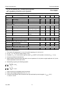
Notes to the characteristics
1. The circuit is DC adjusted at V
P
= 6 to 18 V and AC operating at V
P
= 8.5 to 18 V
2. At 18 V < V
P
< 30 V the DC output voltage ≤ V
P
/2
3. Conditions: V
14
= 0 V; short circuit to ground; switch V
14
to MUTE or ON condition, rise time at V
14
= ≥ 10 µs
4. Frequency response externally fixed
5. Ripple rejection measured at the output with a source-impedance of 0 Ω (maximum ripple amplitude of 2 V) and a
frequency between 100 Hz and 10 kHz
6. Mismatching is given by the following equation:
7. Noise measured in a bandwidth of 20 Hz to 20 kHz
8. Noise output voltage independent of R
S
(V
I
= 0 V)
9. Common mode rejection ratio measured at the output with both inputs tied together. V
I(RMS)
< 3.5 V;
f = 100 Hz - 10 kHz
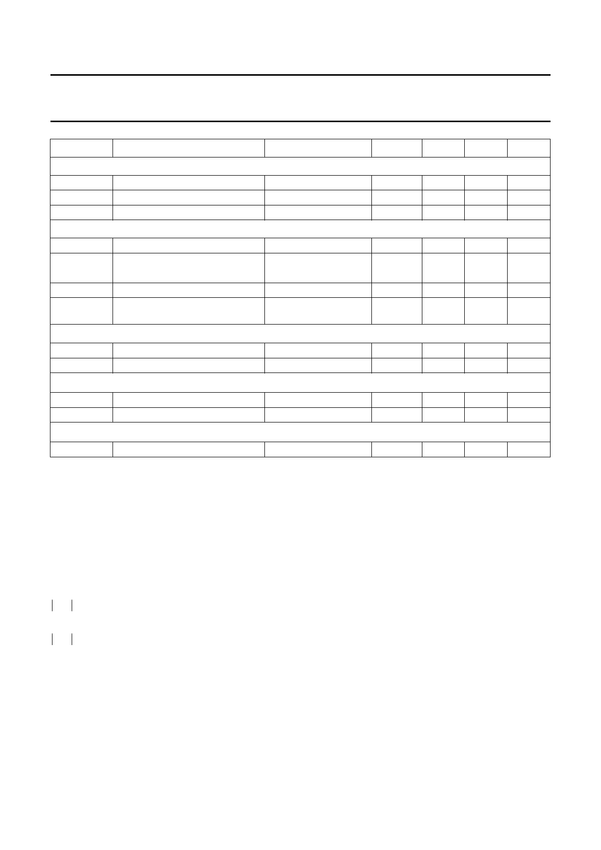
M
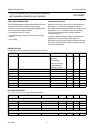
UTE CONDITION
V
mute
mute voltage 3.3 − 6.4 V
V
O
output signal in mute position V
I max
= 1 V; f = 1 kHz −−2mV
V
os
DC output offset voltage −−100 mV
STANDBY CONDITION
V
sb
stand-by voltage 0 − 2V
I
sb
DC standby current V
14
< 0.5 V −−100 µA
0.5 V ≤ V
14
≤ 2.0 V −−500 µA
I
sw
switch-on current − 25 60 µA
I
PSC
supply current short-circuit to ground;
note 3
− 10 - mA
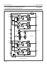
Loudspeaker protection
∆V
6-8, 10-12
DC voltage across R
L
−−1.0 V
t
d
delay time − 0.5 − s
Protection active (∆V
4-6
or ∆V
7-9
≤1.0 V
I
15
current information − 25 −µA
V
15
voltage information 3.6 −−V
Protection inactive (∆V
6-8
and ∆V
10-12
≤0.1 V)
V
15
voltage information −−0.3 V
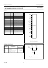
SYMBOL PARAMETER CONDITIONS MIN. TYP. MAX. UNIT
Z
i
∆
Z
i1
Z
i2
–
Z
i1
---------------------
100°
°
⁄×=
Z
i
∆
Z
i3
Z
i4
–
Z
i3
---------------------
100°
°
⁄×=