


July 1994 5
Philips Semiconductors Product specification
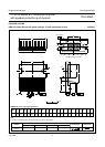
2 x 22 W stereo BTL differential amplifier
with speaker protection and dynamic
TDA1556Q
FUNCTIONAL DESCRIPTION
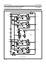
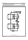
The TDA1556Q contains two identical amplifiers each with
a fixed gain of 26 dB and differential input stages.
The device can be used for bridge-tied-load applications.
The circuit has the following features:
• low stand-by current (< 100 µA)
• low mute/stand-by switching current (low cost supply
switch)
• mute facility
Loudspeaker protection
Should a short circuit to ground occur, thereby forcing a
DC voltage ≥ 1 V across the loudspeaker, a built-in
protection circuit is activated to limit the DC voltage across
the speaker to ≤ 1 V. The delay time of the protection
circuit can be influenced by the external capacitor
connected to pin 15.
A dynamic distortion detector (DDD) is activated when
clipping occurs at one or both output stages. Its
information may be used to operate a sound processor or
DC volume control to attenuate the input signal, thereby
minimizing the distortion.
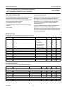
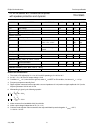
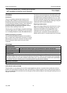
LIMITING VALUES
In accordance with the absolute maximum system (IEC 134)
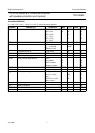
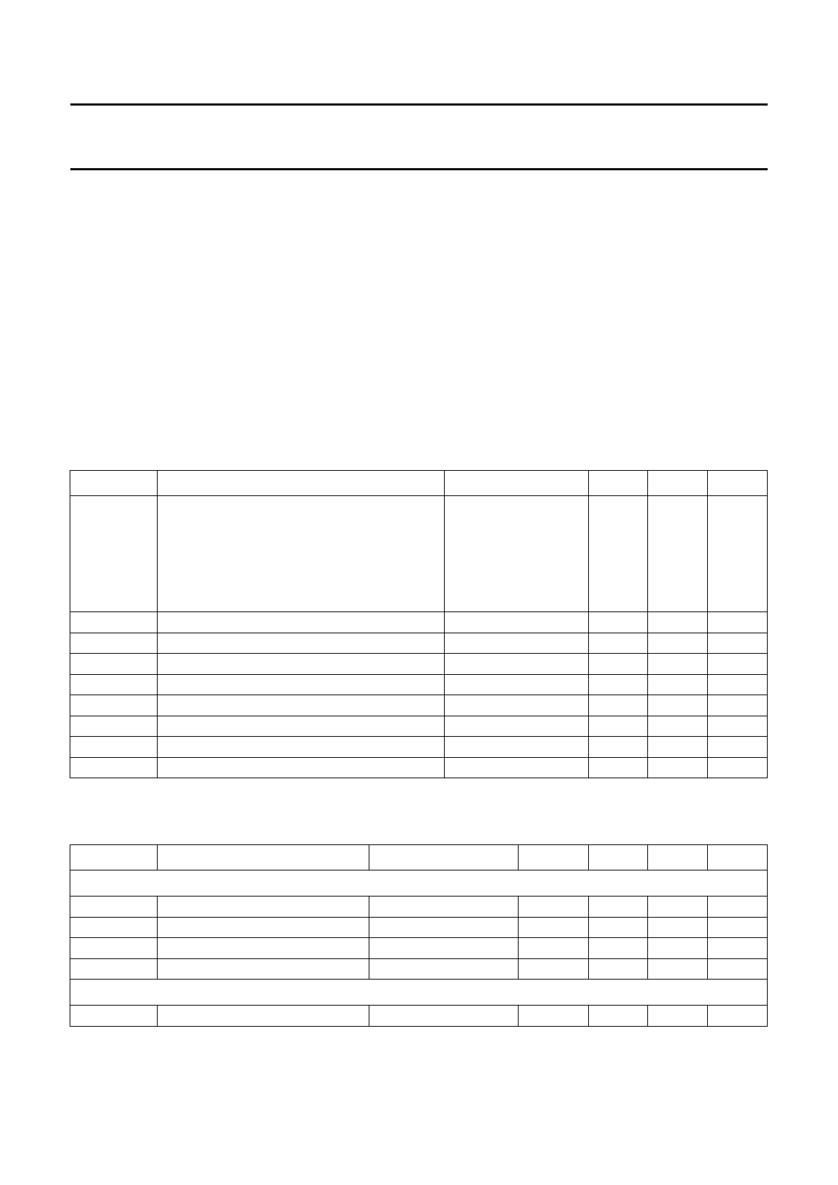
DC CHARACTERISTICS
V
P
= 14.4 V; T
amb
= 25 °C; unless otherwise specified
SYMBOL PARAMETER CONDITION MIN. MAX. UNIT
V
P
positive supply voltage
operating − 18 V
non-operating − 30 V
during 50 ms (load
dump protection);
rise time ≥ 2.5 ms
− 45 V
I
OSM
non-repetitive peak output current − 6A
I
ORM
repetitive peak output current − 4A
T
stg
storage temperature range −55 +150 °C
T
vj
virtual junction temperature − +150 °C
V
psc
AC and DC short-circuit safe voltage − 18 V
energy handling capability at outputs V
P
= 0 − 200 mJ
V
pr
reverse polarity − 6V
P
tot
total power dissipation − 60 W
SYMBOL PARAMETER CONDITIONS MIN. TYP. MAX. UNIT
Supply
V
P
positive supply voltage note 1 6.0 14.4 18 V
I
P
quiescent current − 80 160 mA
V
O
DC output voltage note 2 − 6.9 − V
V
os
DC output offset voltage operating −−100 mV
Mute/stand-by
V
ON
switch-on voltage level 8.5 −−V