


6
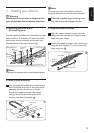
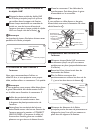
3.4 UHF Dipole and Isolation
Network Assembly
1
Pull the two halves of the UHF dipole away
from the main boom until they lock into the
support bracket.
2 Place each half’s unattached end over one of
the antenna’s lead-in terminals (one for each
half of the UHF dipole on each side of
the boom). 4
D Note
Both bars of the isolation network should
remain parallel to the main boom.
UHF Dipole
Isolation Network
Main Boom
Lead-in Terminal
4
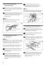
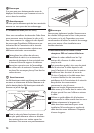
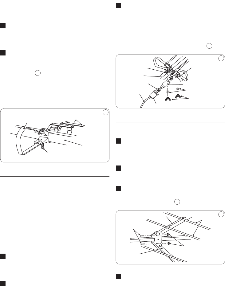
3.5 Connecting Lead-In Cable
to the Antenna
D Note
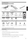
If you prepare your own cable, slide the supplied
matching transformer’s weather boot onto the
cable before you attach the F-connector.
We recommend RG-6 cable, and if you prepare
your own cable, use a quality F-connector.
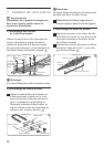
1 Thread the supplied matching transformer’s
spade terminal ends through the antenna’s
strain-relief tab.
2 Slide the spade terminal ends around
the antenna’s lead-in terminals marked
CONNECT LEAD-IN HERE. Secure them
with the supplied at washers and large
wing nuts.
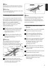
3
Screw the cable’s F-connector onto
the matching transformer. Then slip the
weatherboot over the connection.
D Note
If you use a cable without a weatherboot, cover
the connection with weatherproof tape. 5
Lead-in Terminals
Matching Transformer
Flat Washers
Wing Nuts
Weather Boot
Coax Cable
F-Connector
Plastic Strain-Relief Tab
Spade Terminal Ends
5
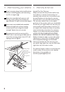
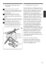
3.6 Unfolding the Antenna Elements
1 Hold each UHF wing boom and turn its
elements until they snap squarely into place
(perpendicular to the boom).
2 Press the supplied small end plugs into the
ends of the wing booms.
3
Fold out the wing booms and secure them
into position using the two supplied 1¼-inch
screws and wing nuts. 6
Wing B
Element
Small Wing Nuts
Wing Boom
Wing Boom
1
1
/
4
-Inch Screws
6
4 Hold the main boom’s elements near the
pivot points and pull them away from the
boom until they snap into the locking
support brackets.