


5
ENGLISH
3 Installing your antenna
B Warning
Installation of this product is dangerous. For
your safety, follow the installation directions.
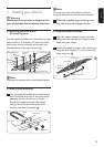
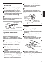
3.1 Splinting the Main Boom
Sections Together
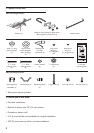
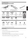
Use the supplied hardware to assemble the main
boom sections. If necessary, lift one end of the
main boom so the crossover wires reach the
threaded posts of the next section. 1
Large Wing Nuts
Flat
Washers
Threaded
Posts
Crossover
Wires
Splint
Large Wing Nuts
1
1
/
2
-Inch Screws
1
D Note
There are no crossover wires over the back section.
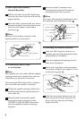
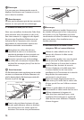
3.2 Mast Clamp Assembly
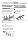
1 Use the supplied hardware to loosely attach
the U-bolt and lock nuts to the mast clamp
assembly on the main boom as shown.
Attach the support boom’s mast clamp,
facing it the same direction as the main
boom’s mast clamp assembly. 2
U-Bolt
Mast Clamp
Lock Nuts
Backup Plate
Main Boom
2
D Note
To access the mast clamp holes, move the
antenna’s elements out of the way as needed.
2 Press the supplied large end plugs into
the main boom and support boom.
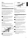
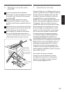
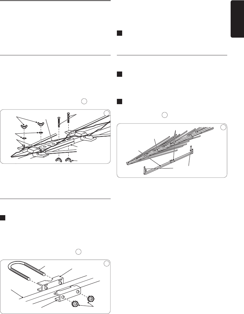
3.3 Support Boom Assembly
1 Align the support boom’s straps and mast
clamp with the main boom’s support strap
holes and mast clamp.
2 Attach the support straps to the main boom
using the two supplied 1½-inch screws and
large wing nuts. 3
Mast Clamps
Main Boom
Support Straps
Support
Boom
3