


Philips Semiconductors Product data
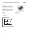
SA58605Dual operational amplifier and 2.5 V shunt regulator
2003 Nov 12
4
MAXIMUM RATINGS
SYMBOL PARAMETER MIN. MAX. UNIT
V
CC
Supply voltage –0.3 +20 V
T
amb
Ambient operating temperature –40 +85 °C
T
stg
Storage temperature –40 +125 °C
P Power dissipation – 250 mW
ELECTRICAL CHARACTERISTICS
T
amb
= 25 °C, V
CC
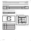
= 5 V (see Figure 6 “Test circuit”, and Table 1 “Parameter test circuit 1 and power supply settings”), unless otherwise
specified.
SYMBOL PARAMETER CONDITIONS MIN. TYP. MAX. UNIT
I
CC
Supply current A
IN
= 0 V; B
IN
= 0 V; R
L
= ∞ – 1.2 1.7 mA
A amplifier
V
o(A)
Output inverting voltage (A) B
IN
= 0 V; R
L
= 4.3 kΩ 2.45 2.50 2.55 V
I
i(bias)(A)
Input bias current (A) B
IN
= 0 V; R
L
= 4.3 kΩ – 30 150 nA
PSSR (A) PSSR (A) B
IN
= 0 V; R
L
= 4.3 kΩ 62 – – dB
I
o(sink)(A)
Output sink current (A) A
IN
= 2.7 V; B
IN
= 0 V; V
OUT
= 1.5 V 5 – – mA
B amplifier
V
o(B)
Output inverting voltage (B) A
IN
= 0 V; R
L
= 4.3 kΩ 151 154 157 mV
I
i(bias)(B)
Input bias current (B) A
IN
= 0 V; R
L
= 4.3 kΩ – 30 150 nA
PSSR (B) PSSR (B) A
IN
= 0 V; R
L
= 4.3 kΩ 65 – – dB
I
o(sink)(B)
Output sink current (B) A
IN
= 0 V; B
IN
= 0.17 V; V
OUT
= 1.5 V 5 – – mA
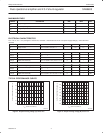
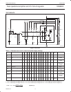
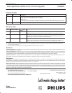
TYPICAL PERFORMANCE CURVES
SL01615
V
CC
, SUPPLY VOLTAGE (V)
246
3.0
2.5
08
OUTPUT INVERTING VOLTAGE A (V)
10 12 14
2.0
1.5
1.0
0.5
0.0
18 20 2216 24 26 28 30
Figure 4. Output inverting voltage (A) versus V
CC
.
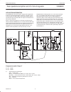
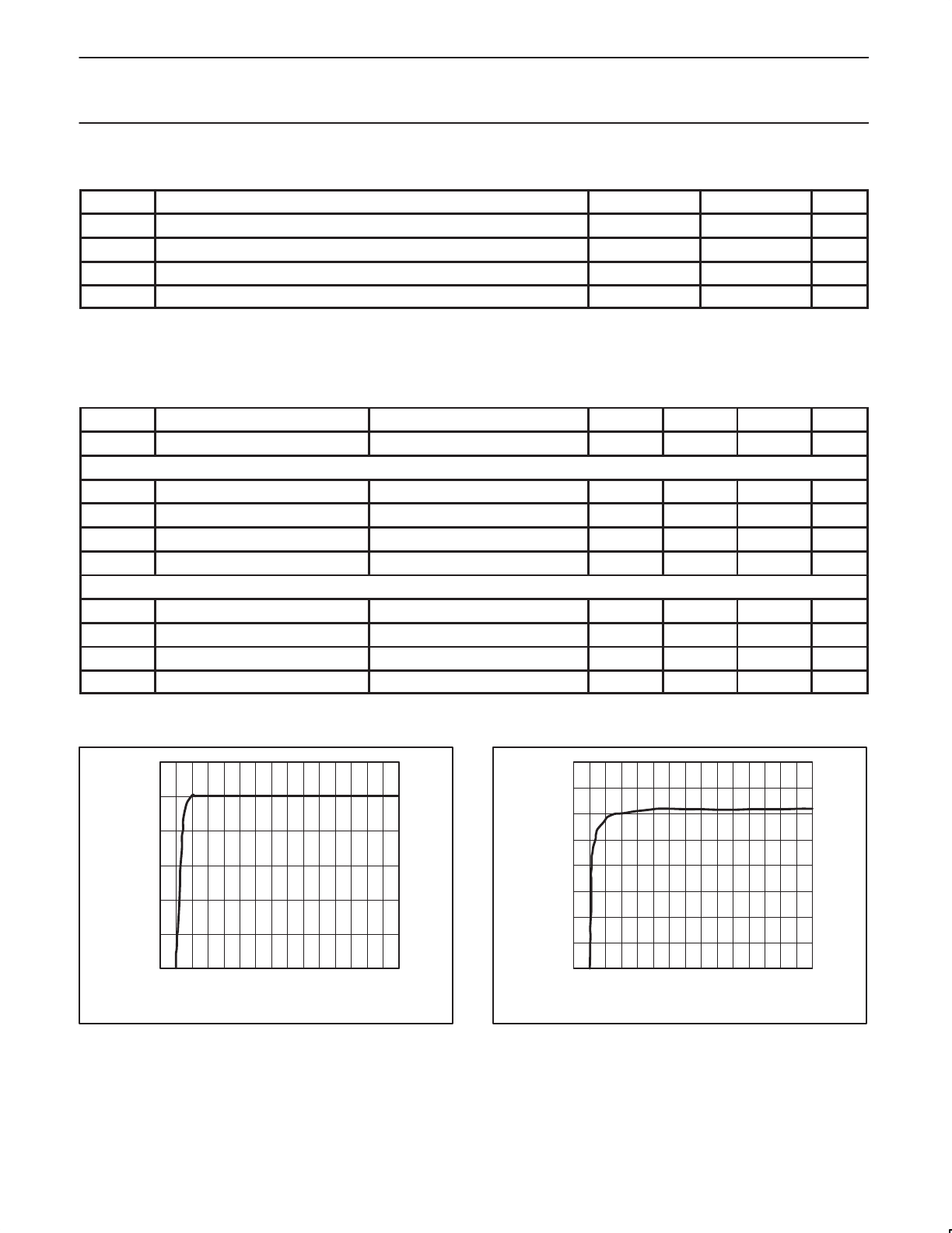
SL01616
V
CC
, SUPPLY VOLTAGE (V)
246
0.20
0.15
0.18
0.13
08
OUTPUT INVERTING VOLTAGE B (V)
10 12 14
0.10
0.08
0.05
0.03
0.00
18 20 2216 24 26 28 30
Figure 5. Output inverting voltage (B) versus V
CC
.