


1998 Feb 12 5
Philips Semiconductors Product specification
Triple video driver hybrid amplifier CR6927
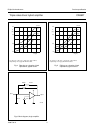
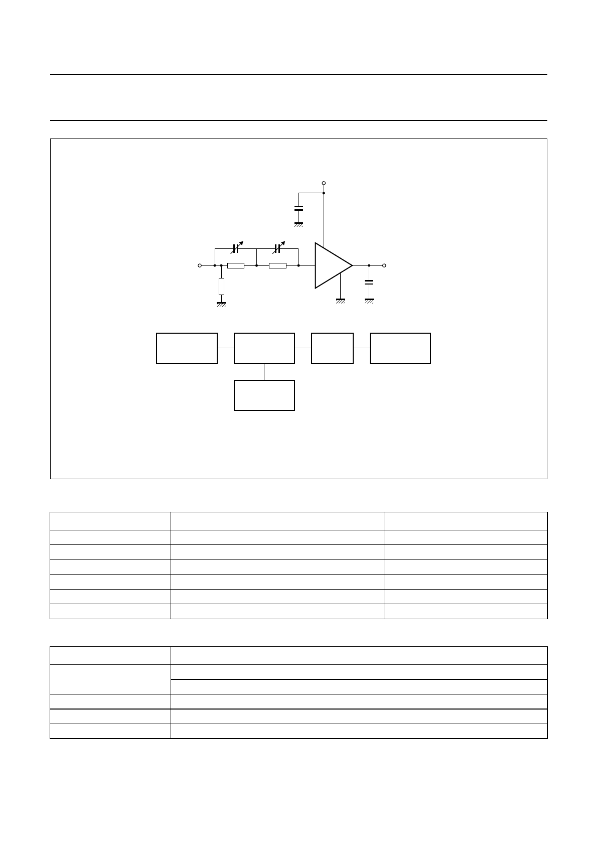
Components used in test circuit (see Fig.7)
Test equipment (see Fig.7)
DESIGNATION DESCRIPTION VALUE
C1 variable capacitor 10 to 160 pF (typ. 68 pF)
C2 variable capacitor 10 to 160 pF (typ. 100 pF)
C3 chip capacitor plus electrolytic capacitor 10 nF plus 4.7 µF; 160 V
R1 resistor 270 Ω
R2 resistor 62 Ω
R3 resistor 50 Ω
EQUIPMENT TYPE DESCRIPTION
Pulse generator Le Croy; Model 9210 with unit 9212
Philips; Model PM5785B (125 MHz) with internal DC offset
Power supply Philips; Model PE1541, 80 V
FET probe Philips; Model PM8943, attenuation 100 : 1
Sampling oscilloscope Tektronix; Model 11803, sampling head SD24
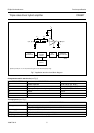
Fig.7 Application test circuit and block diagram.
Speed-up circuit (R1, C1; R2, C2) ensures flat gain over the whole frequency range.
handbook, full pagewidth
CR6927
C2
R2
input
2
1
4
3
output
C
L
C1
R1
R3
MBK283
PULSE
GENERATOR
TEST
FIXTURE
CR6927
POWER
SUPPLY
FET
PROBE
SAMPLING
OSCILLOSCOPE
C3
V
S