


1998 Feb 12 3
Philips Semiconductors Product specification
Triple video driver hybrid amplifier CR6927
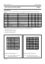
CHARACTERISTICS
V
S
= 85 V; T
C
=25°C; C
L
= 10 pF; output swing = 45 V (p-p) with 42.5 V DC offset (see Fig 7); unless otherwise
specified.
Notes
1. Input signal is a 100 kHz square wave of 3.8 V (p-p) with 1.5 V DC offset (50 Ω source).
2. Sinewave output signal: 1 V (p-p).
3. Measured V
O
/V
I
at input test circuit.
4. Measured V
O
/V
I
at input module.
SYMBOL PARAMETER CONDITIONS MIN. TYP. MAX. UNIT
I
S
supply current open input and open output 85 100 115 mA
P
tot
total power dissipation 25 MHz square wave − 10.6 12 W
t
r
rise time transient response 10 to 90%; note 1 − 2.5 3.1 ns
t
f
fall time transient response 10 to 90%; note 1 − 2.1 2.5 ns
BW small signal bandwidth between −3 dB points; note 2 140 150 − MHz
V
tilt
low frequency tilt voltage 10 kHz square wave − 1.3 1.5 V
V
os
overshoot voltage (rise and
fall time)
adjustable by C1 and C2;
see Fig 7
− 310%
NLN non-linearity V
O
=5to75V − 25%
A
V
DC voltage gain 50 Ω source; note 3 11.2 12.4 13.6
V
G
insertion gain 50 Ω source; note 4 160 180 200
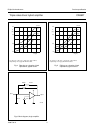
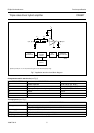
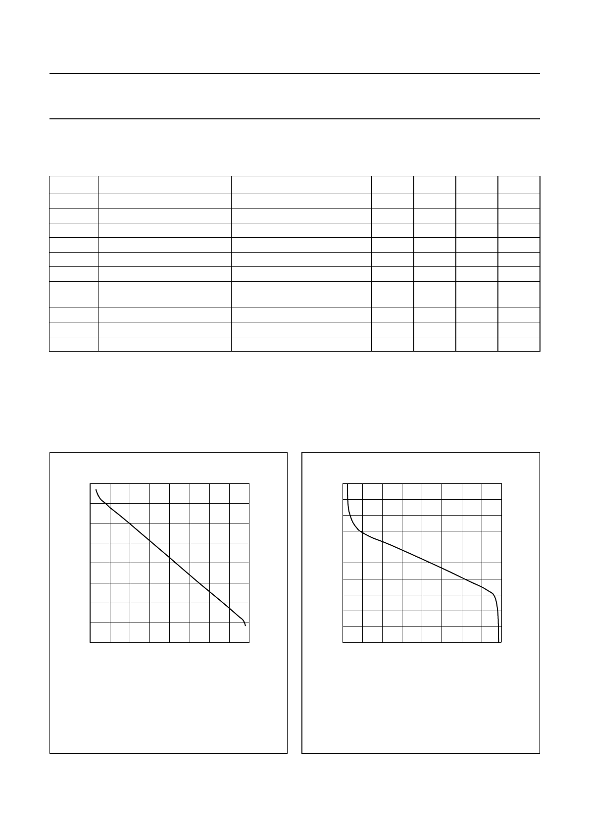
Fig.2 Test circuit input voltage as a function of
output voltage; typical values.
V
S
= 85 V; T
C
=25°C; C
L
= 10 pF; (R1 + R2) = 330 Ω;
output swing = 45 V (p-p) with 42 V DC offset.
handbook, halfpage
020
V
O
(V)
V
I
(V)
40 80
5
3
−1
−3
1
60
MDA185
Fig.3 Input voltage at input module as a
function of output voltage; typical values.
V
S
= 85 V; T
C
=25°C; C
L
= 10 pF; (R1 + R2) = 330 Ω;
output swing = 45 V (p-p) with 42 V DC offset.
handbook, halfpage
02040 80
2
1
V
I
(V)
V
O
(V)
1.8
60
1.6
1.4
1.2
MDA186