


Philips Semiconductors Product data
NE/SA/SE5534/5534ASingle low noise operational amplifier
2001 Aug 03
3
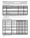
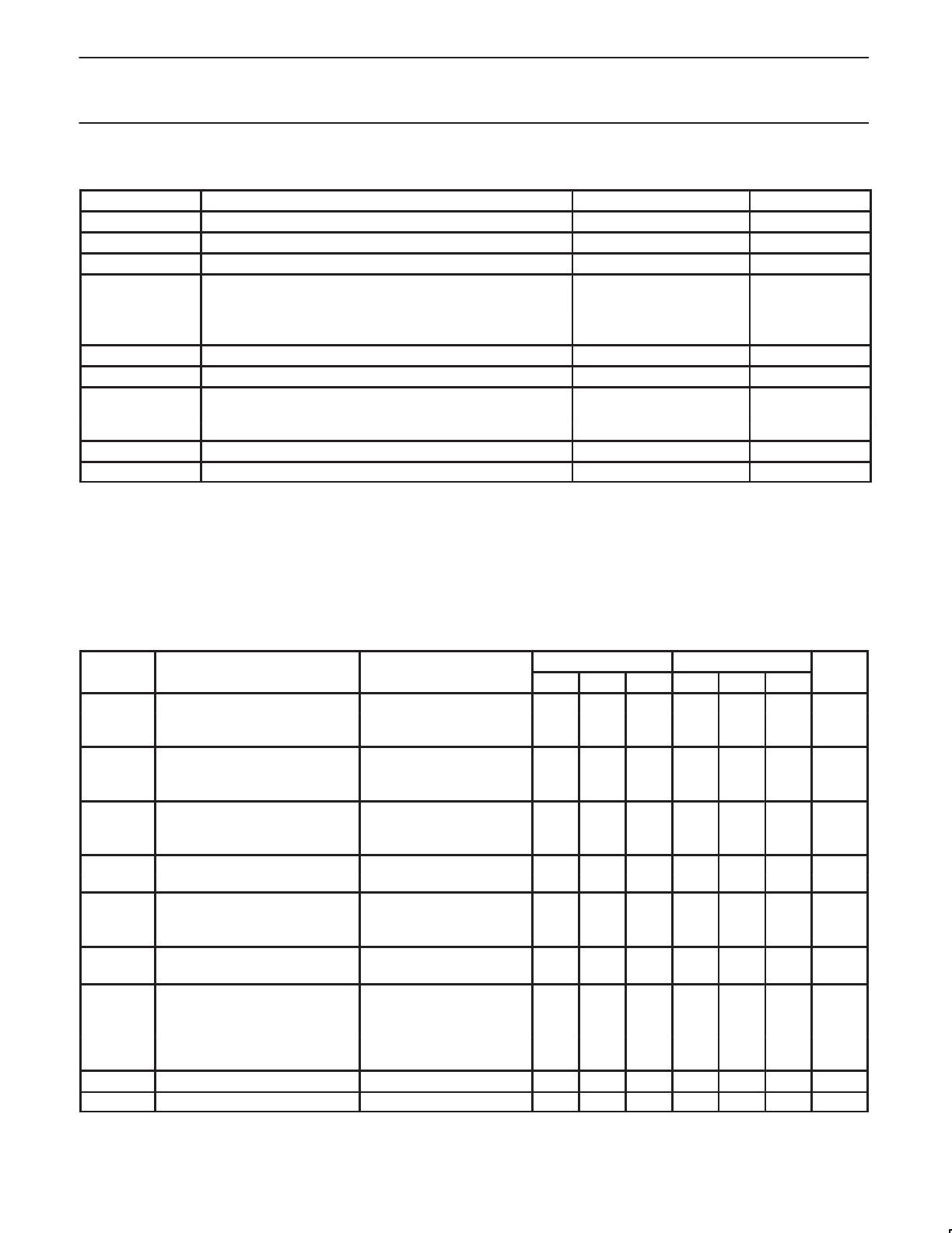
ABSOLUTE MAXIMUM RATINGS
SYMBOL PARAMETER RATING UNIT
V
S
Supply voltage ±22 V
V
IN
Input voltage ±V supply V
V
DIFF
Differential input voltage
1
±0.5 V
T
amb
Operating temperature range
NE 0 to +70 °C
SA –40 to +85 °C
SE –55 to +125 °C
T
stg
Storage temperature range –65 to +150 °C
T
j
Junction temperature 150 °C
P
D
Power dissipation at 25 °C
2
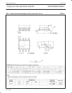
SO8 package 750 mW
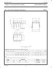
DIP8 package 1150 mW
Output short-circuit duration
3
Indefinite
T
sld
Lead soldering temperature (10 sec max) 230 °C
NOTES:
1. Diodes protect the inputs against over voltage. Therefore, unless current-limiting resistors are used, large currents will flow if the differential
input voltage exceeds 0.6 V. Maximum current should be limited to ±10 mA.
2. For operation at elevated temperature, derate packages based on the following junction-to-ambient thermal resistance:
8-pin plastic DIP 105 °C/W
8-pin plastic SO 160 °C/W
3. Output may be shorted to ground at V
S
= ±15 V, T
amb
= 25 °C. Temperature and/or supply voltages must be limited to ensure dissipation
rating is not exceeded.
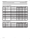
DC ELECTRICAL CHARACTERISTICS
T
amb
= 25 °C; V
S
= ±15 V, unless otherwise specified.
1,
2,
3
SYMBOL
PARAMETER
TEST CONDITIONS
NE/SA5534/5534A SE5534/5534A
UNIT
SYMBOL
PARAMETER
TEST
CONDITIONS
Min Typ Max Min Typ Max
UNIT
V
OS
0.5 4 0.5 2 mV
Offset voltage Over temperature 5 3 mV
∆V
OS
/∆T 5 5 µV/°C
I
OS
20 300 10 200 nA
Offset current Over temperature 400 500 nA
∆I
OS
/∆T 200 200 pA/°C
I
B
500 1500 400 800 nA
Input current Over temperature 2000 1500 nA
∆I
B
/∆T 5 5 nA/°C
I
CC
Supply current 4 8 4 6.5 mA
per op amp Over temperature 10 9 mA
V
CM
Common mode input range ±12 ±13 ±12 ±13 V
CMRR Common mode rejection ratio 70 100 80 100 dB
PSRR Power supply rejection ratio 10 100 10 50 µV/V
A
VOL
Large
-
signal voltage gain
R
L
≥ 600 Ω, V
O
= ±10 V 25 100 50 100 V/mV
A
VOL
Large-signal
voltage
gain
Over temperature 15 25 V/mV
V
OUT
Output swing R
L
≥ 600 Ω ±12 ±13 ±12 ±13 V
Over temperature ±10 ±12 ±10 ±12 V
R
L
≥ 600 Ω; V
S
= ±18 V ±15 ±16 ±15 ±16 V
R
L
≥ 2 kΩ ±13 ±13.5 ±13 ±13.5 V
Over temperature ±12 ±12.5 ±12 ±12.5 V
R
IN
Input resistance 30 100 50 100 kΩ
I
SC
Output short circuit current 38 38 mA
NOTES:
1. For NE5534/5534A, T
MIN
= 0 °C, T
MAX
= 70 °C
2. For SA5534/5534A, T
MIN
= –40 °C, T
MAX
= +85 °C
3. For SE5534/5534A, T
MIN
= –55 °C, T
MAX
= +125 °C