


4
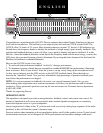
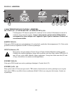
LOW CUT (1)
Provides high pass filtering at 40 Hz in the “in” position. Low frequency roll off is at 12 dB per octave.
LOW CUT LED (2)
With the low cut switch in the “in” position, this LED will illuminate indicating a low frequency roll off at
12 dB per octave at 40 Hz.
BYPASS (3)
In bypass mode (switch in), the input signal is routed directly to the output and is unaffected by all front
panel controls with the exception of the low cut filter.
BYPASS LED (4)
This LED will illuminate when the bypass switch is in the “in” position indicating that the EQ and gain
controls are bypassed.
EQUALIZER SECTION (5)
31-bands of 1/3 octave filters. The filters are constant “Q” devices located at ISO center frequencies. Effec-
tive equalization range is from 20 Hz to 20 kHz. Maximum cut per frequency is 18dB and the maximum
boost per frequency is 12 dB.
AUTOMATIC FEEDBACK LOCATING LEDs (6)
When feedback occurs, the LED of the frequency band that is feeding back will illuminate over the slider
that needs adjusting. The LED will remain illuminated for a few seconds even after the feedback is gone.
This allows you to see where the feedback is if the feedback goes away before any correction is made. If
there is no feedback occurring, all the LEDs will become active, acting as a basic real-time analyzer.
LED LEVEL METER (7)
This multicolored LED ladder indicates output level.
GAIN (8)
Calibrated control for regulating overall gain of an equalizer section. Unity gain throughout the signal chain
may be maintained by recovering lost signal at this point. Example: Assume the equalization process has
introduced a signal loss of -6dB by negative (-) adjustment of the EQ section. The gain should be adjusted
to +6dB to maintain unity gain through the equalizer.
POWER SWITCH (9)
Used to turn AC mains power on or off.