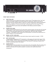
5
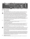
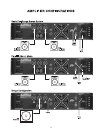
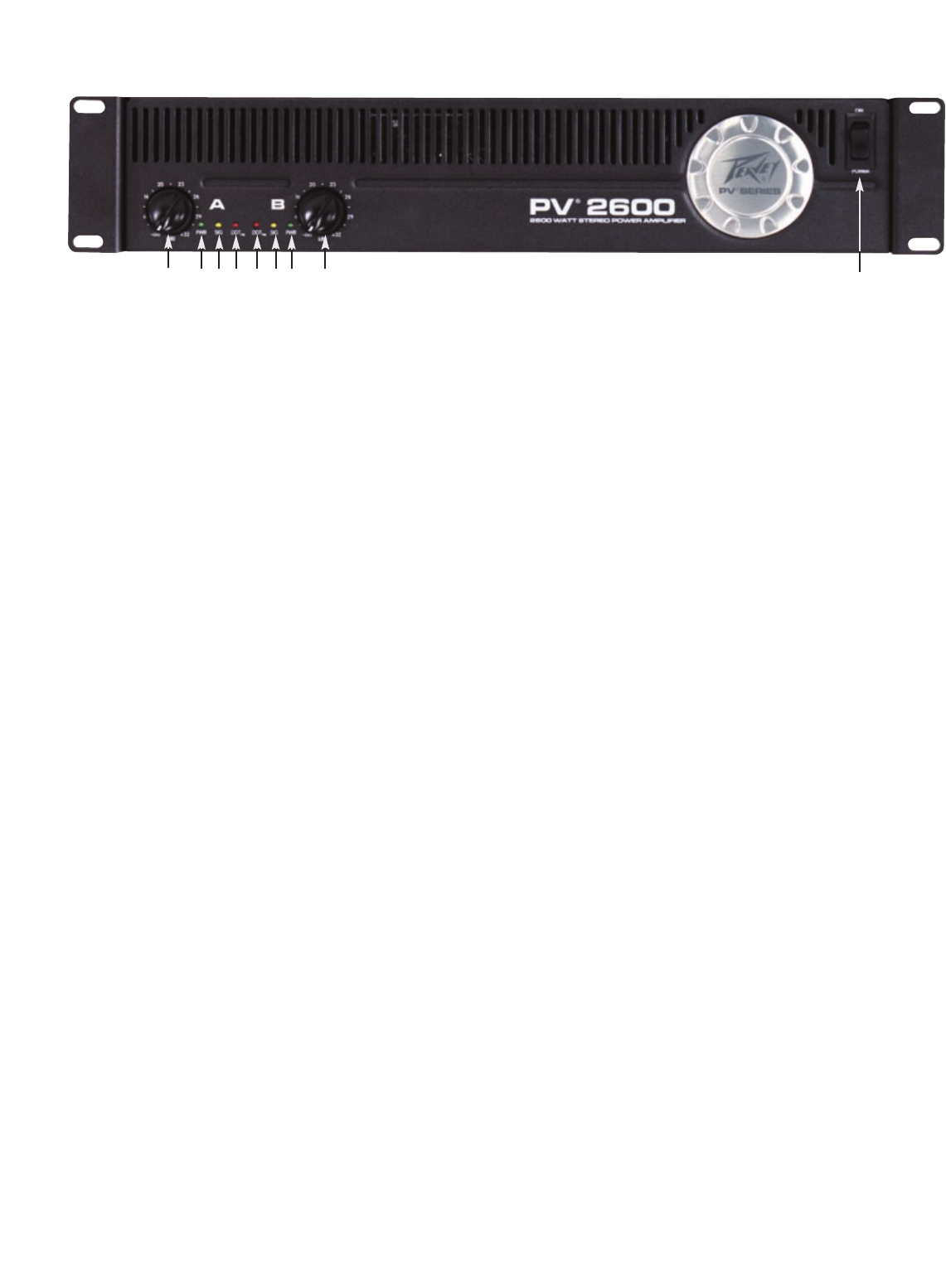
FRONT PANEL FEATURES
(1) INPUT GAIN (dB)
These controls are used to adjust the input gain of each channel. They determine how “loud” each
channel of the power amplifier will sound for a given input signal level. Maximum input gain is
achieved at the fully clockwise setting (+32 dB, 40 X), and this setting yields maximum mixer/system
headroom. A setting of less than fully clockwise will yield lower system noise at the expense of
mixer/system headroom. Turning the control fully counterclockwise is the “off” setting (-∞). It is
always a good idea to power up any new installation at this setting to protect the system
loudspeakers.
(2) POWER LEDS (PWR)
These indicators illuminate when the AC mains power is being supplied to the amp and both channels
are operational. If either channel experiences fault conditions, exceeds safe operating temperature
limits, or if the mains circuit breaker trips; both channel power LEDs will be dark, indicating
“shutdown”. If the BRIDGE mode is selected, the PWR indicator on channel B will remain dark as a
positive indication of this mode selection.
(3) SIGNAL ACTIVITY LEDS (SIG)
These indicators illuminate when the associated channel output signal level exceeds 1 V RMS.
(4) DDT
™
ACTIVE LEDS
These indicators illuminate when DDT compression is taking place in the associated channel. With
the DDT ENABLE / DEFEAT switch on the back panel in the DEFEAT position, these LEDs indicate
clipping is occurring in the corresponding channel. The Peavey DDT compression system will be
covered in greater detail later in this manual.
(5) POWER SWITCH
This heavy-duty, rocker-type switch turns on the mains power to the amplifier. When the mains power
is applied, there is a 3-second delay in activation of the unit. This reduces/eliminates the turn-on
transients associated with the system equipment connected to the amplifier and protects
loudspeakers.
1
2
3
4
4
3
2
1
5


