


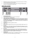
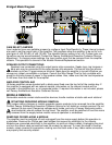
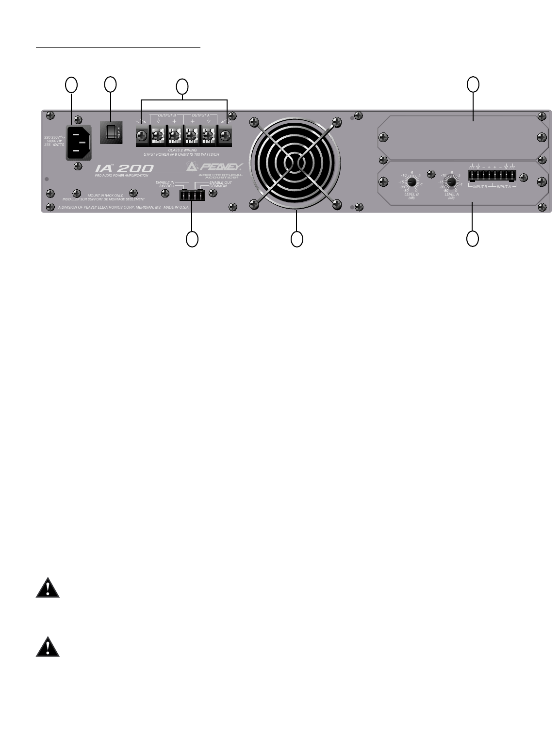
BACK PANEL FEATURES
INPUT AND COMMUNICATION MODULES
The back panels of IA Series amplifiers provide a location to accept plug-in modules. Your amplifier
may have been factory-configured with optional module(s). In this case, information on the relevant
module(s) will be enclosed in the amplifier box, or in a separate binder. If all required information is
not included, please call the Peavey Architectural Acoustics Customer Service department or your
local Architectural Acoustics representative.
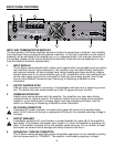
1. INPUT MODULE
The IA Series comes standard with a basic input module which has plugable input connectors
and individual channel rotary attenuators. Your amplifier may have been factory-configured
with optional modules. All input modules have internal voltage gain/input sensitivity jumpers
that are factory-set for an overall amplifier gain of 40. Connections at the input connector per-
mit the audio signal ground to be connected or lifted from the chassis ground. See the sec
tions on
Input Module Connections
and
Removing or Replacing a Module
for more
information.
2. OUTPUT BARRIER STRIP
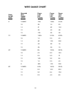
A barrier strip is provided for connection of loudspeakers with bare wire or spade lug connec-
tors. This barrier strip can accommodate up to two 10 gauge wires per terminal.
3. COMMUNICATIONS BAY
A blank panel comes standard with this amplifier. Your amplifier may have been factory-
configured with an optional module. This optional module may be a single communications
module or a dual module which includes signal input and processing functions. See the
section on
Removing or Replacing a Module
for more information.
4. IEC POWER CONNECTOR
A standard IEC power connector is located at the upper left corner of the amplifier back
panel. An AC mains cord having an appropriate AC plug for the intended operating voltage is
included.
5. CIRCUIT BREAKER
A resettable, protective AC circuit breaker is located towards the upper left of the amplifier’s
back panel. If the breaker has tripped, push it back in to return the amplifier to operating con-
dition. If the breaker continues to trip, the amplifier needs servicing. Do not continue to reset
the breaker as severe internal damage and safety hazards could occur!
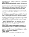
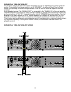
6. SEQUENTIAL TURN-ON CONNECTOR
The IA Series comes standard with remote controllable sequential turn-on enabled by setting
the front power switch to “STANDBY”. The amplifier is activated by applying a voltage
6
1
76
4
35
2