


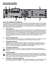
4. Make power connections, allowing for proper current draw. See the section on
AC Mains
Circuit Size Requirements
for more information.
5. Turn the front panel three-position AC switch to “ON,” and bring up the back panel gain
attenuators (if so equipped) to the desired levels.
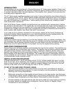
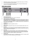
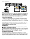
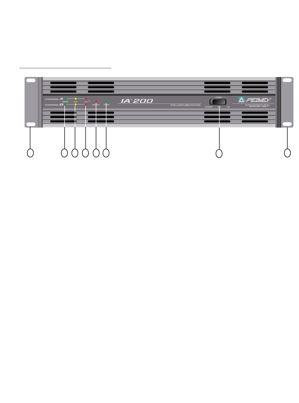
FRONT PANEL FEATURES
1. RACK MOUNTING EARS
Two mounting holes are provided on each front mounting ear.
2. THREE-POSITION AC POWER SWITCH
A three-position switch is on the front panel. With the switch pushed towards the outside pos
tion, the amplifier is “ON”. The middle position is “OFF” and the inside position is marked
“STANDBY”. When switched to “STANDBY”, the amplifier may be activated by the sequential
turn-on circuit or under computer control if so equipped. See the section on
Sequential Turn-
On/Turn-Off
for more information.
3. POWER LED
The Power LED indicates the amplifier is turned on.
4. SIGNAL LED
Each channel has a Signal LED, which comes on when the amplifier output exceeds 1 volt.
5. CLIP LED
Each channel has a “Clip Limiting” LED. This LED illuminates at the clipping point, and indi
cates that internal circuitry reduces amplifier gain to just allow full power. See the section on
Protection Features
for more information.
6. LFC
™
LED
Each channel has a “Load Fault Correction
™
” LED. This LED illuminates whenever the
amplifier channel detects an abnormal load condition. Internal circuitry will instantaneously
reduce the channel gain to allow the amplifier to operate at a safe level into the abnormal
load. See the section on
Protection Features
for more information.
7. PROTECT LED
If the amplifier has just been turned on, or has detected a fault condition, the speaker output
relays will open. This will be indicated by the LED illuminating.
5
1 4 5 6 7 3 1
2