


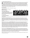

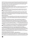
THE S2 OUTPUT MODULE
The S2 output module offers dual Speakon
®
Quick
Connectors and a unique patching capability to
wire these connectors to meet the particular appli-
cation. The Speakon
®
is a four-wire connector with
the connections labeled as 1+, 1-, 2+ and 2-.
Depending upon the loudspeaker needs, these
connections can be used in various ways.
NOTE:
Consult your loudspeaker specifications to determine the wiring configuration
(mode) that will best suit your system.
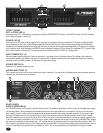
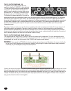
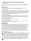
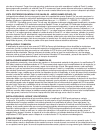
THE S2 OUTPUT MODULE REAR VIEW — STANDARD STEREO MODE (17)
This Speakon
®
wiring arrangement shown below is
as follows: 1+ as the channel signal output and 1- as
the channel chassis ground. This is the de facto
standard for most low-to-medium power loudspeaker
systems. This wiring allows one enclosure to be
connected to Channel A and one enclosure to be
connected to Channel B. The 2+ and 2- connections
are not used in this application. Please notice that
the binding posts on the S2 module also use the
1+ and 1- wiring arrangement. The channel A red
and black binding posts are always connected to the
channel A Speakon 1+ and 1- respectively. Similarly,
the channel B red and black binding posts are
always connected to the channel B Speakon 1+
and 1- respectively.
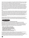
WARNING: The S2 module is shipped with four jumpers plugged in a “storage” configuration across the normally unused 2+ and 2-
Speakon pins. These jumpers are used in other modes of operation following. This “storage” configuration could cause a
shorting problem if a particular loudspeaker system’s Speakon connectors are wired in the high current configuration out-
lined next (1+ and 2+ are connected and 1- and 2- are connected). In this case, we recommend that you remove the
jumpers.
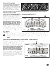
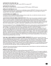
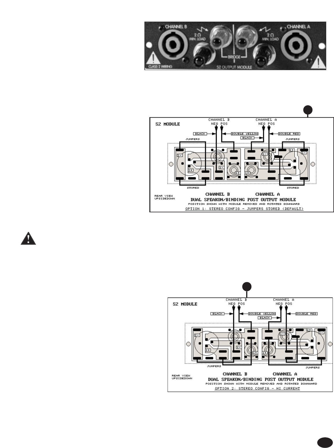
THE S2 OUTPUT MODULE REAR VIEW - HIGH CURRENT STEREO MODE (18)
Many high power loudspeaker systems use the full capability
of the Speakon connector by paralleling 1+ and 2+, and
paralleling 1- and 2-. This wiring improves the current
handling capability of the system and reduces losses. Many
subs with Speakons are wired this way. The S2 module can
be rewired to this configuration using the supplied jumpers
on the rear of the module. Normally, four jumpers are
plugged into a “storage” configuration to prevent losing
them. In this case, one jumper is connected between 1+
and 2+ and another jumper is connected between 1- and
2- for each channel. This is a total of four jumpers. The
following diagram shows the new wiring of the jumpers.
Notice for this mode, the binding post can still be used as
normal outputs for both channels.
7
17
18