


IEC MAINS POWER CONNECTOR (7)
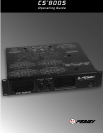
The CS
®
800S is fitted with a universal IEC connector. Into this connector one should always insert a heavy duty #14 AWG 3
conductor line cord with a conventional AC plug with a ground pin. This line cord should be connected to an independent
mains circuit capable of supporting at least 15 amps continuously or greater. This is particularly critical for sustained high
power applications. If the socket used does not have a ground pin, a suitable ground lift adapter should be used and the third wire
grounded properly. Never break off the ground pin on the 3 conductor line cord. The use of extension cords should be avoided, but if
necessary, always use a three-wire type with at least a #14 AWG wire size. The use of lighter wire will severely limit the power
capability of this amplifier. Always use a qualified electrician to install any necessary electrical equipment. To prevent the risk of shock
or fire hazard, always be sure that the amplifier is properly grounded.
DDT
™
SWITCH (8)
This switch is used to either ENABLE or DEFEAT the DDT
™
compressor.
MODE SWITCH (9)
This switch is used to select either STEREO or
BRIDGE mode of operation.
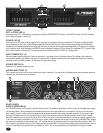
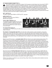
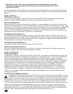
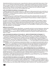
THE B1 INPUT MODULE (10)
The standard input module shipped with each amplifier
is called the B1 MODULE. It offers both XLR electronic
balanced and phone jack quasi-balanced inputs for
each channel using Neutrik's new “combo” connector
to save panel space.
The female XLR inputs (11)
are connected to dual OP AMP circuitry which offers very low noise and extremely high common mode rejection ratio to minimize
outside interference!
The female 1/4" phone jack input (12)
in the center of the “combo” connectors are also connected to a unique “quasi-
balanced” input circuitry. When used, these 1/4" jacks are not “chassis grounded” but connected to ground through a relatively low
impedance circuit which is part of a “ground loop” elimination circuitry associated with the input. This feature will normally allow “hum
free” operation when relatively short 1/4" cable patches are made to this input from various outputs on this amp and other equipment
that share the same rack with this amp. This “quasi-balanced” circuit is “automatic”, and is virtually invisible in normal usage. It cannot
be defeated.
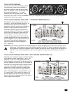
Between the two XLR connectors is a
recessed switch (13)
which allows the user to select the desired polarity (phase) of the
XLR inputs. This switch is a push-push type and a small diameter
“
tool” is required to select the desired position. Set to the out
(default) position, the polarity is pin #3 positive, pin #2 negative, and pin #1 ground. This is the polarity found on most Peavey power
amplifiers. Although this is not the world "standard" (IEC) polarity, it was chosen by Peavey more than 20 years ago, and thus we offer
this polarity to be consistent with products both past and present. If this amplifier is used with other competitive products which use
the IEC standard polarity, then the “in” position of switch (13) should be selected yielding pin #2 positive, pin #3 negative, and pin #1
ground. As with any electronic gear, polarity (phasing) is important because the loudspeaker enclosures associated with this power
amplifier must be in phase with any other loudspeaker enclosures associated with other power amps. If one loudspeaker system were
to “push” while the other “pulls”, then a serious sound “cancellation” could result. Changing the setting of the polarity switch has the
same effect as reversing the polarity of the loudspeaker connections at the output.
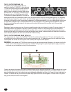
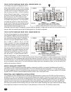
Each channel also has a
female phone jack (14)
labeled “thru”. This jack offers a very flexible patching capability. When the
XLR input connectors (11) are used, then this “thru” jack is the output of the electronic balanced input circuitry, and as such can be
used as a “line out” to connect to the other input jack on this amplifier or other amps in the same rack. Thus, one balanced mixer feed
can be connected to the amp via the XLR connector and then further distributed locally via the “thru” jack. Alternatively, when the 1/4"
phone jack input (12) is used as the input, the “thru” jack becomes a “bridged” input to it (similar to a Y-cord), again allowing this input
signal to be patched to the other input jack on this amplifier or other amps in the system.
Additional input modules are available from your authorized Peavey Dealer. Details of these modules and the installation instructions
can be secured from this source.
5
14
11
12
13
11 12 14