


9
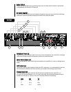
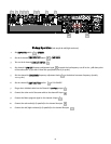
CCrroossssoovveerr AAddjjuussttmmeenntt KKnnoobb ((1133))
The CS 800H is equipped with two independent‚ two-way crossovers adjustable from 40 Hz to 300 Hz.
These crossover frequencies are appropriate for use with a subwoofer system. The output of these
crossovers is selected by the Amp Function switch and connected to the corresponding amplifier
channel. Frequencies above the knob setting will be connected to the corresponding channel when the
Amp Function switch is in the HIGH PASS position. Frequencies below the knob setting will be
connected to the corresponding channel when the Amp Function switch is in the LOW PASS position.
The FULL RANGE position bypasses the crossover.
AAmmpp FFuunnccttiioonn SSwwiittcchh ((1144))
The rear panel Amp Function Select Switch determines whether the associated channel is connected for
full range operation or to the crossover high frequency or low frequency outputs.
LLooww CCuutt SSwwiittcchh ((1155))
The LOW CUT switch is a recessed push switch used to defeat or engage the LOW CUT filter. Pushing the
switch to the in position will engage the filter.
LLooww CCuutt AAddjjuussttmmeenntt KKnnoobb ((1166))
The CS 800H is equipped with two independent low frequency filters. These filters are adjustable from
20 Hz to 100 Hz and are designed to reduce frequencies below those capable of being produced by the
loudspeakers, or to reduce room “rumble.” Frequencies below the knob setting of the corresponding
channel will be attenuated.
HHiigghh PPaassss//FFuullll RRaannggee OOuuttppuutt CCoonnnneeccttoorr ((1177))
The HIGH PASS/FULL RANGE OUTPUT connector function is dependent on the setting of the
corresponding Amp Function switch. This connector allows patching the frequencies above the
crossover knob setting to a secondary amplifier. If the Amp Function switch is in the HIGH PASS
position, the high frequency portion of the crossover will be present at the connector. If the Amp
Function switch is in the FULL RANGE or LOW PASS position, the crossover will be bypassed and allow
patching the full range signal to a secondary amplifier.
LLooww PPaassss OOuuttppuutt CCoonnnneeccttoorr ((1188))
The LOW PASS OUTPUT connector allows patching the frequencies below the crossover knob setting to
a secondary amplifier. This output remains at low frequencies independent of the Amp Function switch
setting.
SSppeeaakkoonn
®®
OOuuttppuutt CCoonnnneeccttoorr ((1199))
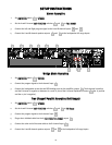
Each channel features a four-wire Speakon connector for the output. In both channels, the 1+ pin is the
channel signal output and the 1- pin is chassis ground. On the Channel A connector, the 2+ pin carries
the Channel B signal output and the 2- pin is chassis ground.
BBiinnddiinngg PPoosstt OOuuttppuutt CCoonnnneeccttoorrss ((2200))
Each channel features a pair of shock-proof binding posts connected in parallel with the Speakon
connector. The red binding posts are the signal output from each channel, and the black binding posts
are chassis ground. For Bridge mode operation, only the red binding posts are used. The Channel A red
binding post should be considered the positive output for the system and should be connected to the
positive input of the associated loudspeaker system.
AACC LLiinnee CCoorrdd CCoonnnneeccttoorr ((2211))
Provided to accept the removable (IEC) type AC line cord. Connect only to proper source (see back panel
markings).