


p.13
features overview
3
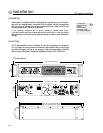
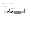
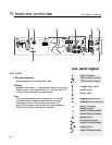
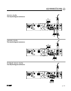
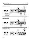
rear panel
4
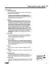
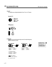
Output connections
Speakers can be connected via the high current binding posts and
the industry-standard Speakon (NL-4) connectors.
Binding posts: One pair (Red- hot, Black- ground) per channel.
Speakons - One connector for each channel.The Speakon
connector for Channel A also contains contacts for Channel B out
put as well (see Operation Modes).
5
Ground lift switch
The recessed two-position ground lift switch is used to isolate the
amp’s signal ground from the chassis/AC ground.The factory default
setting is to the right, Grounded.To lift, or disconnect the signal
ground from the chassis/AC ground,slide the switch to the left.
Never lift the ground prong on the AC connector.
6
Input connections
Input signals can be connected to the amp via the Combi connec-
tors, the 1/4” TRS connectors,and the Female XLR (pin 2 hot) con-
nectors. See Connections
7
Mode selector switch
This recessed,three position switch configures the amplifier for
Stereo, Parallel or Bridged Mono operation. The default factory
setting is Stereo. See - operation modes.
8
Input sensitivity switch
This three position switch allows the user to select the input
sensitivity to .775v (0 dBu), X20,or X40 for full rated output
power.The default factory setting is X20.
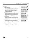
Never connect a hot
(red) output to ground
or to another hot (red)
output!
a
Do not adjust the mode
selection switch while
the amplifier is turned-on.
a
In situations where an UNBAL-
ANCED signal is fed to the amp, it’s
important to ground the unused
input. If the inverting (-) input of an
amp channel is left floating, the chan-
nels gain will drop by 6 dB. In effect,
the amp will not be as loud. For more
information about this, ask your dealer
or contact Crest Audio Technical
Support directly.
Never connect a speaker of LESS
than 2Ω minimum impedance to an
individual channels’ output connections
when operating in STEREO or PARAL-
LEL mode.
Never connect a speaker of LESS
than 4Ω minimum impedance to
Channel A and B “+” output connec-
tions when operating in BRIDGE
mode. In BRIDGE mode operation, the
amplifier can produce output voltages
exceeding 120VRMS. Use extreme cau-
tion.
a
a