


2
p. 5
installation
Make certain that there
is enough space around
the front and rear of the
amplifier to allow the
heated air to escape.
suggestion: In racks
with closed backs
allow at least
one
standard-rack-space
opening for every four
amps.
a
cooling requirements
The CC
™
Series amplifiers use a forced-air cooling system to maintain a low, even
operating temperature. Air is drawn into the amplifier by fan(s) on the rear panel,
courses through the cooling fins of the tunnel-configured channel heat sink(s), and then
exhausts through the front panel grille. If a heat sink gets too hot, its sensing circuit
will open the output relay, disconnecting the load from that particular channel. The CC
1800 utilizes one common heat sink and a single fan, but retains the separate circuitry.
It is important to have an adequate air supply at the back of the amplifier and enough
space around the front of the amplifier to allow the cooling air to escape. If the amp
is rack mounted, do not use doors or covers on the front of the rack; the exhaust air
must flow without resistance. If you are using racks with closed backs, use fans on the
rear rack panel to pressurize the rack and ensure an ample air supply.
operating precautions
Make sure the mains voltage is correct and is the same as that printed on the rear of
the amplifier. Damage caused by connecting the amplifier to improper AC voltage is
not covered by any warranty. See the Connecting Power section for more information
on voltage requirements.
Although the CC Series amplifiers have AUTORAMP
™
circuitry, which raises the signal
level gradually after the output relay closes, it is always a good idea to have the gain
controls turned down during power-up to prevent speaker damage if there is a high
signal level at the inputs. Whether you buy or make them, use good-quality connections,
input cables and speaker cables, along with good soldering technique, to ensure
trouble-free operation. Most intermittent problems are caused by faulty cables.
Consult the Wire Gauge Charts to determine proper gauges for different load
impedances and cable lengths. Remember that cable resistance robs amplifier power in
two ways: power lost directly to resistance (I
2
R loss), and by increasing the impedance
of the load presented to the amplifier, thereby decreasing the power demanded of the
amplifier. Also make sure the mode switch is correctly set for the desired application.
See Sections on Stereo, Parallel and Bridged Mono Operation for more information.
Always turn off and
disconnect the amplifier
from mains voltage
before making audio
connections. Also, as an
extra precaution, turn the
attenuators down during
power-up.
a
+
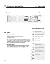
connecting inputs
Input connections are made via the 3-pin XLR (pin 2+) or 6.3 mm plug “Combi”
connectors on the rear panel of the amplifier. The inputs are actively balanced. The
input overload point is high enough to accept the maximum output level of virtually
any signal source.
connecting outputs
All models have two output (speaker) connections per channel. Cables can be
connected with banana plugs, spade lugs, or bare wire to the five-way binding posts.
The preferred method is connection via the Speakon connectors.