


p.15
features overview
3
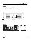
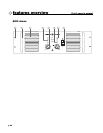
rear panel
3
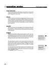
Female Balanced XLR Input Connectors
4
Male Balanced XLR Input Connectors
These connectors accept input signals on balanced male and female
XLR input plugs. Connectors for each channel are in parallel; any
unused
XLR connectors may be used for daisy-chaining input connec-
tions to other amplifiers.
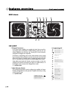
In Parallel and Bridge Mono mode a signal applied to channel A’s input
connectors will appear also at channel B’s.
5
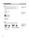
Input Sensitivity/Gain Switch
The Pro II Series amplifiers come standard set to x40 gain.
The Input Sensitivity/Gain switch allows the user to select either
.775
(0dB) sensitivity, x40, or x20 gain.
6
Fan Inlet Ports and Filters
Cooling air enters the amplifier through the fan inlet ports located on
the rear of the amplifier chassis.Be sure not to block these ports when
installing the amplifier or other associated equipment.Air must flow
unimpeded.Fan filters
(removable without tools) are provided to min-
imize entry of dust and dirt.
7
Input XLR Polarity Switch
Pro II Series amplifiers are supplied standard with the XLR configured
as Pin 2 hot
(
+
). Use the XLR polarity switch to change this setting to
Pin 3 hot
(
+
) if desired.
8
Signal Ground-Lift Switch
The recessed signal ground-lift switch electrically connects signal
ground to the chassis/
AC ground. This switch is factory-set to the
ground position
(bottom). The top position lifts the amplifier’s signal
ground.In a properly designed system
(for safety purposes and to min-
imize noise
),amplifiers should be connected to ground through the AC
line cord.
Whenever possible, the signal source equipment should share the
same
AC ground as the amplifier. In some cases this may not be possi-
ble, and a ground loop results. If this happens, the first step is to move
the ground-lift switch to the lifted position
(top).In this position,the sig-
nal ground is lifted and completely isolated from the chassis/
AC
ground. Do not change the switch to the lifted position if the amplifi-
er and the signal source equipment are on the same
AC ground.
Should the ground loop problem persist after the ground-lift switch
has been set to the lifted position, then the shield on balanced input
lines should be grounded at one end only
(usually the signal source).
Never connect a hot (red)
output to ground or to
another hot (red) output!
a