


11
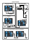
CONNECTING A SIGNAL TO THE IMPULSE
®
12D
There are a variety of ways to input a signal to the Impulse
®
12D. The two inputs (7,8) provide either a balanced
mic- or line-level input, allowing the use of a 1/4” TRS (ring-tip-sleeve) type phone plug OR a male XLR plug, as
well as a 3-conductor Euro-style jack connector (9) on input 1.
Unbalanced inputs are also provided, as the ¼” input (7,8) can take a standard single-ended (tip-sleeve) phone
plug. Alternatively, the RCA phono jacks (10) of input 2 can be used. The RCA jacks do not provide a Left and
Right stereo input, as the Impulse
®
12D is a monophonic sound source. Instead, the two jacks mix and buffer
any two RCA sourced signals and send them on to the Gain control of input 2 (14).
Do not connect cables to the jacks while the unit is ON with the Gain knob(s) turned up! While a standard
single-ended 1/4” phone plug-equipped cable will work well and the balanced input circuitry of the inputs (7,8)
will provide some interference rejection, a balanced cable using either the balanced TRS 1/4” phone plug or the
XLR plug will provide superior interference rejection and performance.
Sometimes, with difficult interference problems, it will be helpful to lift the shield ground on a balanced cable at
the Impulse
®
12D end by only using the ground lift switch (4). Check any input changes carefully, always turning
the gain control down before plugging and unplugging cables or engaging the ground lift switch.
Use of high quality, premium cables is recommended for the Impulse
®
12D, as these usually have better
shielding and materials and will provide greater long-term reliability. The best option is a shielded, balanced
XLR cable no longer than necessary to reach the Impulse
®
12D. It is usually a good idea to leave some slack
at the input to the Impulse
®
12D and also to tape the cables down or run them under a cable guard to avoid
anyone tripping over them or pulling the Impulse
®
12D over when stand mounted.
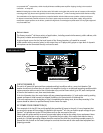
GAIN CONTROL ADJUSTMENT
The Impulse
®
12D is equipped with a Gain control (13,14) on each of the two input channels to facilitate use
in many different applications. With the Gain control adjusted fully clockwise, gain is at maximum and the
input sensitivity is 0.200 V RMS for full-rated output. When driving the Impulse
®
12D from a mixer, it may be
advantageous to reduce the input sensitivity by turning the Gain control to the halfway point. The Impulse
®
12D
will now more closely match a typical power amp.
If the mixing board indicates clipping of its output signals, then all of the Impulse
®
12D power capability is not
being utilized cleanly. Clipping the signal before it gets to the Impulse
®
12D is not optimal. Reduce the mixer
output level and turn up the Gain control(s) on the Impulse
®
12D.
The amplifiers in the Impulse
®
12D are equipped with DDT
™
and multiple LED indicators to show that DDT
™
has
engaged (15,16, front grille logo).
If the sound seems heavily compressed, check these indicators; if it is blinking RED more than occasionally,
then the drive level from the mixer (or the Gain control/s {13,14} on the Impulse
®
12D) needs to be reduced.
When first turning on the sound system, switch on all upstream electronics first, then the Impulse
®
12D with
its Gain control(s) fully counterclockwise (all the way down). Begin checking levels with the mixer output level
controls all the way down, and bring them up slowly with the Impulse
®
12D Gain control/s set to the desired
setting (one-third of the way up is recommended to start).
It is not good practice to turn the Gain control(s) on the Impulse
®
12D all the way up and then try to control level
only from the mixer, as this approach would tend to pick up excess noise. The best practice would be to run a
“hot” signal from the mixer down the cable to the Impulse
®
12D, and then turn the Impulse
®
12D Gain control
up only as much as necessary to reach full desired output. With this approach, it is necessary to verify the mixer
output is not clipping.
If a particular input channel is unused, the best practice is to turn the Gain knob all the way down, or fully
counter-clockwise. This minimizes any possible noise pick-up from the unused channel.
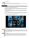
MIC/LINE SWITCH ADJUSTMENT
The mic/line switch (5,6) provides for the increased gain needed for microphone use into the two inputs.
Set the Mic/Line switch to “in” for line-level signal use and set it “out” for mic-level use. The associated LED
indicator (11,12), which is located to the upper right of the switch, will glow green for a line-level setting and red
for a mic level setting.