


6
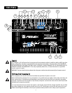
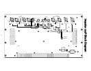
PPoowweerr SSwwiittcchh ((33))
This rocker switch applies mains power to the Impulse 115P when in the ON position.
PPoowweerr LLEEDD ((44))
This LED illuminates when the preamp electronics receive power and when the Power Switch is in the On
position.
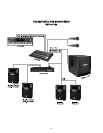
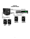
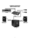
IInnppuuttss ((55))
The left (5a) and right (5b) channel input jack groups consist of a combo female XLR and 1/4" TRS
connector and a male XLR running in parallel. This arrangement allows the audio input signal to be daisy-
chained. In other words‚ you could hookup other power amps‚ powered speakers‚ more Impulse 115Ps or
other devices. Unbalanced‚ left and right RCA-type input jacks (5c) are also provided for CD players or
similar units. A mono switch (5d) feeds the left input to both channels when not running in stereo mode.
The adjacent‚ yellow LED (5e) lights when the unit is placed in mono mode.
MMaasstteerr SSyysstteemm LLeevveell ((66))
When used in conjunction with the
kkoossmmooss
controls (7)‚ this knob controls the overall system gain
(volume) of the Impulse 115P. The adjacent‚ red LED (11) indicates activation of the built in DDT
compression. See number (11) below for more details on DDT compression.
kkoossmmooss ((77))
The
kkoossmmooss
is a low-frequency energy and stereo imaging enhancement system that turns the minor
shocks of an input signal into a sound that is off the Richter scale. And‚ it’s included in the Impulse 115P.
The Quake/Sub level knob (7a) sets the powered subwoofer output and simultaneously sets the amount
of
kkoossmmooss
Quake function. The Xpanse knob (7b) controls the amount of high frequency expansion
applied to the high-pass outputs (8) or the speaker level outputs (9). The bypass switch (7c) bypasses the
kkoossmmooss
entirely. When in bypass mode‚ the Quake/Sub level knob sets the powered subwoofer level
without any
kkoossmmooss
effect. The adjacent‚ blue LED (7d) lights up when the kosmos kicks in.
HHiigghh--ppaassss OOuuttppuutt ((88))
These left and right‚ line-level‚ high-pass filtered outputs are also controlled by the Master System Level
control (6). They provide a 120 Hz high-pass output for a powered speaker system or a power amp and
passively crossed over speaker system.
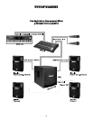
SSppeeaakkeerr LLeevveell PPoowweerreedd OOuuttppuuttss ((99))
The left and right speaker level outputs allow connection of a left and right‚ passive speaker system to
provide a complete stereo sound reinforcement or DJ system. This signal is passively high-pass filtered to
protect the speakers from excessive low bass.
GGrroouunndd LLiifftt SSwwiittcchheess ((1100))
These switches provide for breaking ground loops on the input channels (10a) or the high-pass outputs
(10b). Leave these in the normal position unless there is a need to break such a ground loop (i.e. unusual
system hum or noise). They can be switched independently.
DDDDTT LLEEDD ((1111))
This LED will light at the onset of clipping. If the LED is flashing quickly and intermittently‚ the unit is just
reaching the clipping threshold. A steady‚ bright glow means the unit is clip-limiting‚ or reducing gain to
prevent severely clipped waveforms from reaching the speakers. During initial power-up‚ the DDT LED will
light‚ indicating the RampUp
™
gain-reduction circuitry is activated.