Page 10
ultimately we found that we could operate it without feedback as long as we put a healthy bias
current through it. For these amplifiers this is about 600 watts worth. This is not pure Class A
operation in the context of 1000 watts output, but it has proven to be the appropriate amount.
The result is a series of amplifiers using the supersymmetric topology delivering up to 1000
watts per channel into 8 ohms with good distortion and noise figures. If you are a little less
fussy about distortion, you will get twice that into 4 ohms. This is accomplished with only two
gain stages and no feedback.
People inevitably will ask how this relates to bridged amplifiers in general, and the balanced
amplifier offerings of other companies. It is similar in that both terminals of the output to the
speaker are “live”; neither of them is grounded.
The supersymmetric amplifier is a special subset of balanced amplifiers, unique and covered
by U.S. patent. Supersymmetry is an approach that truly takes advantage of balanced
operation like no other and requires a balanced input to retain the precisely matched behavior.
Supersymmetry is ideally used to obtain high quality performance from very simple circuit
topologies, avoiding the high order distortion character and feedback instabilities of complex
circuits. A single gain stage amplifier using this approach can perform as well as a two gain
stage design, and a two gain stage version of this topology can outperform the four or five
stages of a conventional amplifier.
Here is some more explanation of the details of its operation:
The supersymmetry topology does not use operational amplifiers as building blocks, nor can it
be represented with operational amplifiers. It has two negative inputs and two positive outputs
and consists of two matched gain blocks coupled at one central point where the voltage is
ideally zero. The topology is unique in that at this point, the distortion contributed by each half
appears out of phase with the signal, and we use this to reinforce the desired signal and
cancel noise and distortion. This occurs mutually between the two halves of the circuit, and
the result is signal symmetry with respect to both the voltage and current axis, and anti-
symmetry for distortion and noise. This means that the distortion and noise of each half
appears identically and cancels.
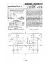
The diagram on the patent cover sheet shows an example of this topology. Each of the two
input devices 20 and 21 are driven by an input signal, and their outputs run through a folded
cascode formed by devices 30 and 31 to develop voltages across current sources 34 and 35.
The sources 20 and 21 are coupled through resistor 40 which is the sole connection between
the two halves and which also sets the gain of the circuit.
The gates of the input devices 20, 21 are virtual grounds, and ideally would be at absolutely
zero voltage. However, as the gain stage is not perfect, finite distortion and noise voltages
appear at these points. These appear at the other side through resistor 40, in phase at the
output of the other half of the system, where they match the distortion and noise of the first
half.
By actual measurement, this circuit does essentially nothing to reduce the distortion and noise
in each half. Distortion curves before and after supersymmetry is applied are nearly identical.
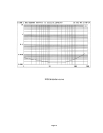
The distortion curves of the circuit from the patent cover sheet show: (a) the intrinsic distortion
of each half of the example circuit, (b) the distortion of the differential output lowered due to the


