IA EC106 UK.INDD RH 02.06
Power Amplifier f. Pressure-/Flow Valves
Series EC106Installation Manual
8
Parker Hannifin GmbH & Co. KG
Hydraulic Controls Division
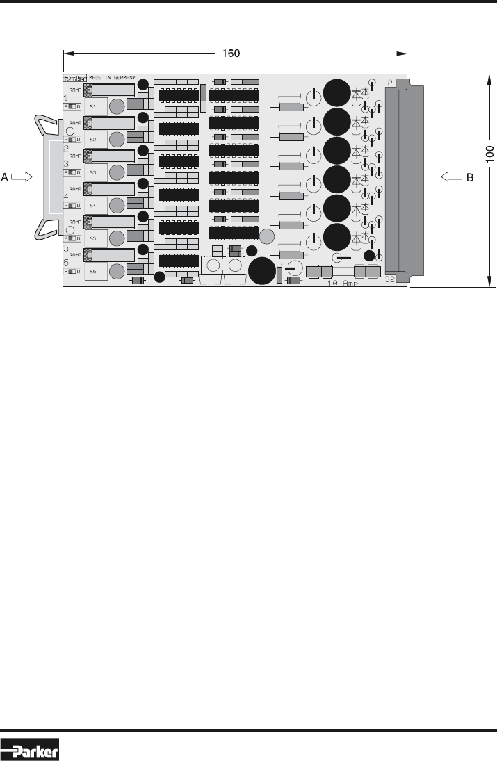
Dimensions
(Euro card)
Installation guide to electronic modules to provi-
sion of electromagnetic compatibility
Power Supply
The utilized power supply has to comply with the
EMC-standards.
Relais and solenoids operating from the same
supply circuit as the valve electronics have to be
fitted by surge protection elements.
Wiring Cable
The wires between the installation site of the module
and the peripheral units, as power supply, valve sole-
noids, command signal source have to be shielded.
The following wire sizes must be reached: power
supply and solenoids AWG 15, other connections
AWG 20. The capacity should not exceed a value of
approx. 130 pF/m (wire/wire). The maximum cable
length is 50 m. No power current lines may be placed
within the wired shielded cables to the electronic
module. The cable shield has to be connected to
ground at both ends (see also chapter “Grounding“).
Please be aware of ground loops.
Installation
The module has to be mounted within a conductive,
shielded enclosure. Usable is i.e. an EMC-approved
control cabinet. A perfect grounding of the enclosure
is mandatory (see also chapter “Grounding“).
Grounding
The mounting plate of the valve has to be connected
to the grounded metal machine frame. The cable
shields must be tied to ground at the control cabinet.
A low-ohmic potential compen-sation wire has to
be provided between the control cabinet and the
machine frame (cable wire >AWG 7 cross section)
to prevent ground loops.


