


7
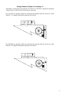
Configuring the Zamp v.2 for Mono operation
1. Turn the unit off.
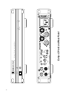
2. Connect the single cable from your mono source to the Right channel Input jack.
3. Set the Stereo-Mono Switch to its Mono position.
4. Connect the positive lead of the speaker wire to the red R+ channel speaker terminal.
5. Connect the negative lead of the speaker wire to the red L+ channel speaker terminal.
Note: the R+ and L+ terminals are not spaced to accept a dual banana plug.
Automatic Turn On Options
For automation and convenience, the Zamp v.2 can be turned on and off by applying a
voltage to the Trigger In jack or by the presence of an audio signal at the input.
Auto On Select Switch
In the right position of the Auto On Switch, the Zamp v.2 is triggered on and off with an
external +9 V to + 12 V voltage. When the external voltage ceases the Zamp v.2 will turn
off immediately.
In the middle position of the Auto On Switch, the auto on function is disabled and the
Zamp v.2 can only be turned on and off manually by the On-Off button on the front panel.
In the left position of the Auto On Switch, the Zamp v.2 is turned on and off when an
audio signal is present at the Left and Right Input jacks. When the audio signal ceases, the
Zamp v.2 will remain on for about five minutes. This prevents unwanted turn off during
pauses in the music.
Trigger Input Connection
The Zamp v.2 can be triggered on with an external DC voltage source from +9 V to
+12 V. Many audio video controllers, and all Parasound audio video surround controllers
produced since 1997, include trigger outputs for this task.
To activate the Zamp v.2 with an external voltage source, plug one end of the provided
cord to the +12 V Trigger Input of the Zamp v.2 and the other end to the source
component’s +12 V output. Parasound sources will have a matching 2.5mm jack, but if
the source trigger is a terminal, you can cut off the plug at one end and attach the bare
wires. The lead with the white stripe on it corresponds to the plug’s tip and the unmarked
lead corresponds to the sleeve of the plug.
If the trigger voltage source is DC, the trigger plug tip must be positive and its sleeve
negative. The trigger circuit is optically coupled and thus only draws 15 mA of current for
activation.