


8
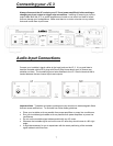
Audio Output Connections
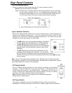
The JC 3 Output Jacks connect to the input jacks on your line level preamplifier. Each JC 3
module has two Output jacks, one Balanced XLR jack and one Unbalanced RCA jack. The
balanced and unbalanced jacks are active simultaneously. If your preamplifier is equipped
with balanced inputs we recommend using the JC 3 Balanced XLR output jacks for best
possible signal-to-noise ratio and best rejection of external noise sources.
Note: The JC 3 uses a fully differential balanced output circuit and does not employ phase
inverters. The JC 3 does not invert polarity.
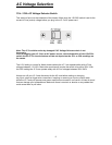
Each channel module has a 3 position input load switch. Select the setting that matches your
turntable cartridge type. If you are unsure which setting is best for your equipment you might
want to contact the cartridge manufacturer. You may also try all three settings and use the
setting which sounds the best.
The MM setting is for moving magnet cartridges. It provides a 47k ohm load and
appropriate gain for all MM cartridges.
The MC 100 setting is for most moving coil cartridges. It provides the higher gain
required for low output or high output MC cartridges with a 100 ohm load that is ideal
for nearly all MC cartridges.
The MC 47k setting provides the appropriate gain for MC cartridges with an
alternative 47k ohm load. You can try both the 100 or 47k settings to see which
sounds best in your system
.
The MC 47k setting is also the recommended load for MI (moving iron) cartridges,
such as Grados.
Other Connections
12V In Jack
The JC 3 12V input uses a mono 3.5mm sub-mini jack. To automatically trigger the JC 3 on
and off, insert the trigger wire plug into this jack and plug the other end into your
preamplifier’s 12V trigger output jack. When the JC 3 Turn On Options switch is set to 12V
the JC 3 will turn On and Off with your preamplifier.
If the preamplifier’s trigger output is a + and - terminal, you can cut the 3.5mm plug off one
end of the included trigger wire and strip off about ¼” (6mm) of insulation. Attach the bare
wires to the + and - terminals. The conductor with the white stripe on its insulation
corresponds to the plug’s tip (+) and the conductor with the unmarked lead corresponds to
the plug’s “sleeve” (-).
Note: The Model JC 3 trigger circuit draws a negligible 15 mA from the preamplifier.
12V Loop Out Jack
The Trigger Out jack lets you loop or “daisy-chain” the incoming trigger voltage to another
component.
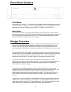
AC Power Cord
The IEC standard AC cord supplied with your JC 3 is an audiophile-grade component.
Please connect it directly to an AC wall outlet or power conditioner that is always “live.” If
possible, plug your JC 3 into the same AC outlet that your preamplifier is plugged into. If
different AC outlets are used for the JC 3 and the preamplifier the ground potential may be
higher or lower between the outlets, resulting in audible hum.