


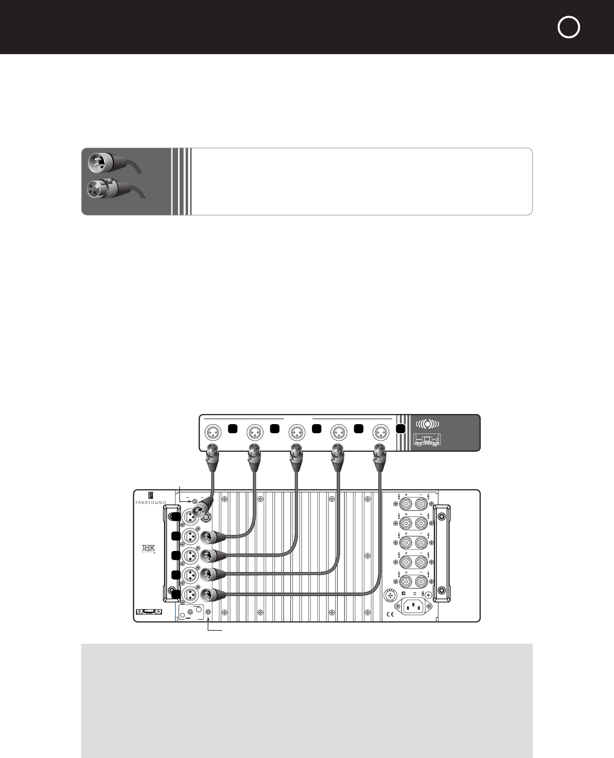
CONNECTING A SURROUND CONTROLLER
TO THE BALANCED INPUTS ON YOUR A 51
Left and Right Balanced Input Jacks
Balanced connections will give you the best sound. If your surround controller has balanced
XLR output jacks, we recommend that you connect them to these inputs. Refer to the Balanced
and Unbalanced Lines in the Technically Speaking section for additional information about why
we recommend using balanced lines.
What You’ll Need:
•
Five balanced interconnect cables with XLR connectors
•
A surround controller with balanced output connectors
Before Connecting
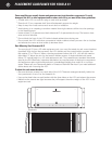
❑ Leave the A 51’s AC cord disconnected until you have made all other connections to prevent
any surprise burst of sound.
❑ Make sure that all your cables are long enough so they are not strained or stretched once they
are connected.
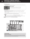
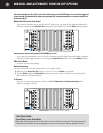
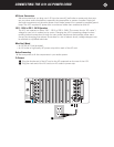
❑ Make sure the Balanced - Unbalanced Input Select switch on the rear of the A 51 is in its
Balanced (left) position and the Ground switch is in its Normal (down) position.
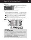
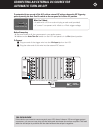
To Connect
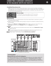
1 Plug the male end of the first balanced interconnect cable into the Balanced Ch 1 input
jack on the A 51.
2
Plug the female end of the cable into the balanced output jack for the channel on your
surround controller that you wish to correspond to Ch 1 on your A 51.
3
– 0 Repeat steps 1 and 2 above to connect Ch 2, Ch 3, Ch 4, and Ch 5.
3
Parasound Products, Inc.
San Francisco, CA USA
Manufactured under
license from Lucasfilm
Ltd. Lucasfilm and THX
are registered Trademarks
of Lucasfilm Ltd.
CAUTION
To Prevent Electric Shock,
Do Not Remove Cover. No
User-Serviceable Parts Inside,
Refer Servicing To Qualified
Service Personnel.
L U C A S F ILM
LM
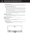
A51 Amplifier
WARNING
To Prevent Fire Or Shock
Hazard, Do Not Expose This
Unit To Rain Or Moisture.
AC 115V 60Hz
AC 230V 50Hz
Power Consumption: 1800W
Input
12 V
Man
Audio
50 mV 250
Ground
Normal
Lift
Auto Turn On
Sensitivity
Fuse
T15A/250V1-115V Area
T8A/250V-230V Area
Ch 1
Ch 2
Ch 3
Ch 4
Ch 5
Balanced Unbalanced
Input Select
SURROUNDŁ
CONTROLLER
OUTPUTS
2 4 6 8 10
1
3
5
7
9
Input Select Switch,
set to left position
Ground Switch, set to down position
YOU SHOULD KNOW
Balanced XLR Jacks and Their Pin Configuration
The balanced inputs of the A 51 use XLR jacks that conform to the industry standard of:
Pin 1: Ground, Pin 2: Positive (+), Pin 3: Negative (--). The balanced outputs on some
components use terminals with 3 screws instead of XLR jacks. These are compatible
with the A 51 as long as you match the bare wires to the corresponding pins on the XLR
plug: + to pin 2, - to pin 3, and Ground to pin 1.
XLR Connectors
Male
Female