


TECHNICALLY SPEAKING
13
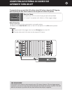
Audio Trigger Sensitivity Adjustment
The Audio Sensitivity Control sets the threshold of the
audio trigger signal. You can adjust this level from a
maximum sensitivity of 50 mV (fully counterclockwise)
to a minimum sensitivity of 250 mV (fully clockwise).
If you set this control to 50 mV, the A 51 might be
falsely triggered on by non-musical or noisy signals that
can appear in the system, such as when you switch
preamp inputs at high volume levels. If you set this
control to 250 mV, the A 51 might not turn on during
quiet musical passages. The detented position (click
stop) at 12 o’clock corresponds to 100 mV. It’s a good
starting point and will be suitable for most systems.
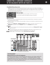
Balanced and Unbalanced Lines
Recording and broadcast studios use balanced con-
nections exclusively because of their inherent ability
to reject noise and hum, thus assuring the best
sound. Certain high quality preamplifiers and surround
controllers built for residential use utilize balanced
connections with XLR jacks for the same reasons.
All Parasound Halo series power amplifiers have bal-
anced inputs with XLR jacks so you can take full
advantage of their inherent noise reduction capability
and superior sound quality.
Unbalanced connections with RCA jacks are found on
all home audio equipment. RCA jacks and two-conduc-
tor wires are less costly than the additional circuitry,
higher priced XLR connectors and three-conductor
wiring required for balanced connections.
In an unbalanced line, the positive audio signal appears
at the center pin of the RCA jack and the negative
signal on the outer shield wire, which also functions as
the ground connection. Unbalanced interconnect cables
are vulnerable to hum from an AC line, or other noise,
such as RF (Radio Frequency), which can be reproduced
through your loudspeakers. Since the unbalanced line’s
ground also carries the audio signal, there is no way
for the connected amplifier or preamplifier to distinguish
between the audio signals you want and unwanted
noise emanating from external sources.
Balanced lines are superior because they utilize separate
conductors for audio and ground: two inner conductors
carry the positive and negative audio signal, and a third
outer wire connects the grounds and also shields the
two signal conductors. When the positive and negative
signals appear at the component receiving the signal
they are equal, but 180 degrees out of phase with each
other with respect to ground. To send and receive bal-
anced signals requires special differential circuitry.
A differential input circuit amplifies only the difference
between the positive and negative signals. For exam-
ple, when a 1 Volt signal arrives at a balanced input
stage, the differential input “sees” a positive 1 Volt
minus a negative 1 Volt, or 2 Volts total. External hum
and noise that somehow gets into a balanced line is
common to both its positive and negative conductors
with respect to ground. Therefore, it is canceled or
rejected by the differential input circuit.
This phenomenon of rejecting noise signals common
to both positive and negative conductors is called
common mode rejection. Differential inputs are speci-
fied according to how well they reject signals common
to both conductors. This is measured in dB and is
called the common mode rejection ratio or CMRR.
Bare Speaker Wire Ends
If you plan to use connections with bare wire ends, use
a wire stripper to remove just enough insulation to
expose a 1⁄2" (13 mm) length of bare wire. You can insert
the stripped wire into the hole that goes sideways
through the terminal
’s metal post. Before inserting the
wire, twist its bare strands to prevent any of the strands
from making contact across the two speaker terminals.
If you have a soldering iron, you can “tin” (apply a small
amount of molten solder) to each stripped bare wire to
prevent it from unraveling, fraying and oxidizing.
Speaker Wires - Banana Plugs Instead of Bare Ends
For convenience, we’ve supplied ten gold-plated
banana plugs with your A 51. To attach these plugs, first
pull the flexible red and black insulators off the plugs
and slide them on the + and - speaker wires. Next, use
a wire stripper to remove insulation to expose about
3/4" (19mm) of bare wire. Insert the bare wire into the
barrel of the banana plug and crimp the barrel down
with a pliers or crimper to hold it in place. Finally, slide
the colored insulator down the wire so it is over the
barrel of the plug. The only exposed metal should be
the tip of the plug.
Choosing Interconnect Cables and Speaker Wire
We are often asked to recommend specific brands of
interconnect cables and speaker wire. It’s true that
with some amplifiers, sound quality will vary greatly
according to interconnect cables and speaker wires.
However, Parasound amplifiers use robust circuitry
that sounds superb regardless of interconnects and
speaker wires. Therefore, we feel that choosing a
brand of cable for Parasound amplifiers is purely a
matter of personal taste.
Ground Loops - Eliminating Hum and Buzz
Audible hum and buzzing noises in a system are usu-
ally related to issues with the component grounds.
Ground (sometimes called common) is a point of
reference for voltages in virtually all audio and video
components. Ground is supposed to remain at zero
volts while the audio signal swings positive (voltage
above ground) and negative (voltage below ground).
If ground isn’t at zero, there can be an audible 60 Hz