


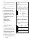
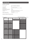


Night mode
11
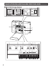
!4 Day/Night Selection Switch (DAY/NIGHT)
In the Day mode, you will not hear the beep tone of the
other lane in the headset that sounds when the vehicle
detector is on and that sounds when you press the but-
ton T of the order taker unit.
In the Night mode, you will hear the beep tone of either
lane in the headset when the vehicle detector of either
lane is on. Once you press the button T, you will no
longer hear your lane’s beep tone. However, you will
continue to hear the other side’s beep tone when the
other side vehicle detector is on, until the button T of
the other side’s order taker unit is pressed.
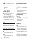
Note: The following is the beep patterns.
Beep A: Pi...Pi...
Beep B: PiPi...PiPi...
Beep C: Pi..PiPi...Pi..PiPi...
State of lane
Vehicle detec-
tor at Lane A is
ON.
Vehicle detec-
tor at Lane B is
ON.
A Beep A
Order
taker unit
Beep A
B
Beep A Beep A
A
Beep B Beep B
B Beep B Beep B
Vehicle detec-
tors of both
lanes are ON.
A Beep C
(When you press
the button T, the
beep tone will be
deactivated.)
Beep C
(When you
press the
button T,
Beep C will
change to
Beep B.
B
Beep C
(When you press
the button T, the
beep tone will be
deactivated.)
Beep C
(When you
press the
button T,
Beep C will
change to
Beep A.
!8 Remote Speaker Terminals
(REMOTE SPEAKER: H, GND)
These terminals are used for the connection with
Remote Speaker.
The audio level is 8 Ω, 3 W, unbalanced.
Note: The remote speaker is a locally procured acces-
sory.
!9 Double Drive Through Control Output Terminals
(DDT CONTROL: OUT, GND)
To compose Double Drive Through of two center mod-
ules, these terminals are used for the connection with
the DDT (IN, COM) terminals of the other center mod-
ule.
• The DDT CONTROL OUT terminal is connected
with the DDT IN terminal of the other center mod-
ule.
• The DDT CONTROL GND terminal is connected
with the DDT COM terminal of the other center
module.
@0 Auxiliary Input Terminals (AUX INPUT: H, C, GND)
These terminals are used for the connection with the
line or the connection with a gooseneck microphone.
Note: When connecting the gooseneck microphone,
set the AUX IN SEL switch to G/MIC.
@1 Gooseneck Microphone PTT Terminals
(G/MIC PTT: IN, COM)
These terminals are used for the connection with the
PTT cable of a gooseneck microphone (locally pro-
cured).
@2 Vehicle Detector Terminals
(V/DET: IN, COM)
These terminals are used for the connection with the
output terminal of vehicle detector.
@3 Double Drive Through Control Input Terminals
(DDT: IN, COM)
To compose Double Drive Through of two center mod-
ules, these terminals are used for the connection with
the DDT CONTROL (OUT, GND) terminals of the other
center module.
• The DDT IN terminal is connected with the DDT
CONTROL OUT terminal of the other center mod-
ule.
• The DDT COM terminal is connected with the DDT
CONTROL GND terminal of the other center mod-
ule.
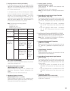
@4 Transformer Terminals
(TRANSFORMER 12V AC: GND, LOAD)
These terminals are used for the connection with WX-
C516 Power Transformer.
!5 Order Taker Unit Talk Lock Release Switch
(O/T TALK LOCK RELEASE)
This switch is used to release temporarily the talk lock
mode of the order taker unit.
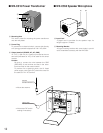
!6 Menuboard Microphone Terminals
(MENU BOARD MIC: H, C, GND)
These terminals are used for the connection with
Menuboard Microphone (Speaker Microphone WX-
C550).
The audio level is –61 dBV, 8 Ω, balanced.
!7 Menuboard Speaker Terminals
(MENU BOARD SP 8 Ω: H, C, GND)
These terminals are used for the connection with
Menuboard Speaker (Speaker Microphone WX-C550).
The audio level is 8 Ω, 3 W, unbalanced.
Day mode