ENGLISH
RQTV0247
13
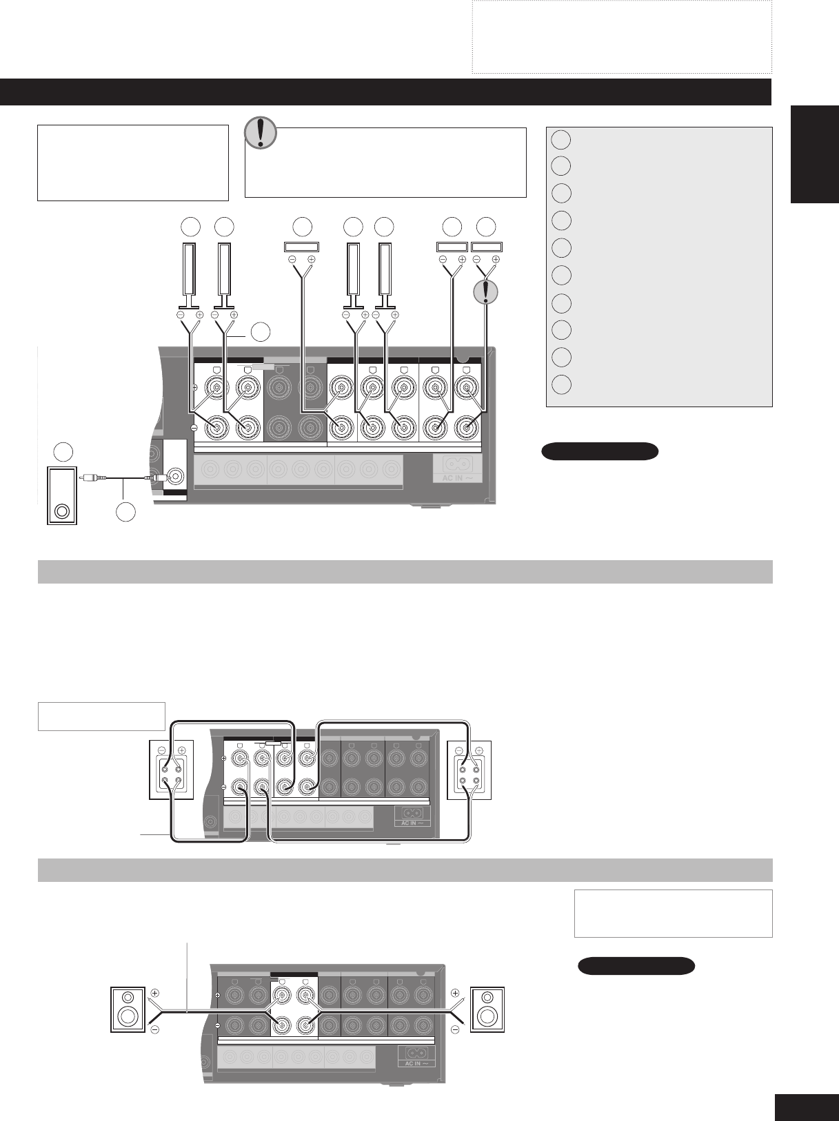
Speaker connections
(TV/STB)
OPTICAL1
Y PB PR Y YPB PR PB PR
LF HF
DIGITAL IN
(DVD RECORDER)
(DVD PLAYER)
(CD)
OPTICAL2 COAXIAL1
COAXIAL2
OUT (DVD RECORDER)IN
SVIDEO
OUT
TV MONITOR
IN
DVD PLAYER
IN
DVD RECORDER
IN
TV/STB
OUT
VIDE
O
TV MONITOR DVD PLAYER
IN IN
DVD RECORDER
IN
VCR
IN
TV/STB
L
R
IN
CD
CENTER
SUBWOOFER
SURROUND
FRONT
DVD/DVD 6CH IN
AUDIO
IN
DVD RECORDER
IN
VCR
IN
TV/STB
OUT
SUBWOOFER
LR
FRONT A FRONT
B
LR
CENTER SURROUND
LR
SURROUND BACK
LR
TV MONITOR OUT DVD RECORDER IN
COMPONENTVIDEO
TV / STB IN
BI-WIRE
LOOP
EXT
LOOP
EXT
LOOP
EXT
AM ANTFM ANT
LOOP ANT
GND
SPEAKERS
A OR B / BI-WIRE (4-16Ω EACH SPEAKER) A AND B (6-16Ω EACH SPEAKER)
(6-16Ω EACH SPEAKER)
If you have a single surround back speaker,
connect it to the SURROUND BACK (L)
terminal .
Speaker cable
Front speaker (R)
Front speaker (L)
Center speaker
Surround speaker (R)
Surround speaker (L)
Surround back speaker (R)
Surround back speaker (L)
Monaural connection cable
Active subwoofer
Turn off all components before making any connections.
Peripheral equipment and cables sold separately unless
otherwise indicated.
To connect equipment, refer to the appropriate operating
instructions.
•
•
•
Connecting speakers
Front speakers (left , right )
Place either side of the television, then adjust their position and angle towards the
seating position until you are satisfied with the relationship between the images and
sound.
Center speaker ( )
Place directly above or below the center of the television, aiming at the seating position.
Surround speakers (left , right )
Place on either side of or slightly behind the seating area, about one meter higher than
ear level.
Surround back speakers (left , right / when you connect only one
speaker )
Place behind the seating area, about one meter higher than ear level.
Subwoofer ( )
Place anywhere near the television (but not so close as to cause excessive vibration).
1
When only SPEAKERS B is on, output
will be 2-channel only. Signals from
multi-channel sources are “down-
mixed” and output through the two front
speakers you have connected.
Note
(TV/STB)
OPTICAL1
Y PB PR Y YPB PR PB PR
BI-WIRE
LF HF
DIGITAL IN
(DVD RECORDER)
(DVD PLAYER)
(CD)
OPTICAL2COAXIAL1
COAXIAL2
OUT (DVD RECORDER) IN
S VIDEO
OUT
TV MONITOR
IN
DVD PLAYER
IN
DVD RECORDER
IN
TV/STB
OUT
VIDEO
TV MONITOR DVD PLAYER
IN IN
DVD RECORDER
IN
VCR
IN
TV/STB
L
R
IN
CD
CENTER
SUBWOOFER
SURROUND
FRONT
DVD/DVD 6CH IN
AUDIO
IN
DVD RECORDER
IN
VCR
IN
TV/STB
OUT
SUBWOOFER
LR
FRONTA FRONTB
LR
CENTER SURROUND
LR
SURROUND BACK
LR
TV MONITOR OUT DVD RECORDER IN
COMPONENT VIDEO
TV / STB IN
LOOP
EXT
LOOP
EXT
LOOP
EXT
AM ANTFM ANT
LOOP ANT
GND
SPEAKERS
A OR B / BI-WIRE (4-16Ω EACH SPEAKER) A AND B (6-16Ω EACH SPEAKER)
(6-16Ω EACH SPEAKER)
HF
HF
LF
LF
Speaker impedance
Front A: 4 to 16 Ω
Center: 6 to 16 Ω
Surround: 6 to 16 Ω
Surround back: 6 to 16 Ω
Rear panel
After changing your speaker set up:
Perform auto speaker setup
(➡ pages 14 to 16) or automatic speaker
detection (➡ page 17); or for manual
settings (➡ page 27).
Note
Connecting biwireable speakers
Biwireable speakers have separate terminals for the high frequency and low frequency
signals.
Use this connection to reduce interference between the high frequency and low frequency
signals for high-fidelity sound.
When you are playing analogue or 2-channel PCM sources, the unit can allocate an amplifier
each to the high frequency and low frequency signals, thereby giving you a much clearer bi-
amp stereo sound (➡ page 20).
HF stands for high frequency and LF for low frequency.
•
•
•
Front speaker
(R)
Rear view
Front speaker
(L)
Rear view
Speaker cable
Speaker impedance
BI-WIRE: 4 to 16 Ω
Be sure to connect the HF cables
to the FRONT B terminals, and
the LF cables to the FRONT A
terminals, so that you can correct
any delay that may occur
(➡ page 28).
To take advantage of this
connection and ensure the
best possible sound, be sure
to change the setting in “LR BI-
WIRE setting” to “YES”
(➡ page 27).
•
•
2
3
4
5
6
7
8
9
10
1
2 3 4 5 6 7 8
9
10
Connecting a second pair of front speakers
This second set of terminals allows you to connect a second pair of speakers to place in
another room, for example.
To use the speakers connected to the FRONT B terminals, press [SPEAKERS B] (➡ page 20).
(TV/STB)
OPTICAL1
Y PB PR Y YPB PR PB PR
BI-WIRE
LF
HF
DIGITAL IN
(DVD RECORDER)
(DVD PLAYER)
(CD)
OPTICAL2 COAXIAL1
COAXIAL2
OUT (DVD RECORDER)IN
S VIDEO
OUT
TV MONITOR
IN
DVD PLAYER
IN
DVD RECORDER
IN
TV/STB
OUT
VIDEO
TV MONITOR DVD PLAYER
IN IN
DVD RECORDER
IN
VCR
IN
TV/STB
L
R
IN
CD
CENTER
SUBWOOFER
SURROUND
FRONT
DVD/DVD 6CH IN
AUDIO
IN
DVD RECORDER
IN
VCR
IN
TV/STB
OUT
SUBWOOFER
LR
FRONT
A
FRONTB
LR
CENTER SURROUND
LR
SURROUND BACK
LR
TV MONITOR OUT DVD RECORDER IN
COMPONENT VIDEO
TV / STB IN
SPEAKERS
LOOP
EXT
LOOP
EXT
LOOP
EXT
AM ANTFM ANT
LOOP ANT
GND
A OR B / BI-WIRE (4-16Ω EACH SPEAKER) A AND B (6-16Ω EACH SPEAKER)
(6-16Ω EACH SPEAKER)
Rear panel
Front speaker (L)Front speaker (R)
Speaker cable
Rear panel
Speaker impedance
Front A and B: 6 to 16 Ω
Front B: 4 to 16 Ω
For your reference
SA-XR59 (RQTV0247-B).indb 13 6/5/2007 9:10:47 AM


