


RQT7694
6
Installation des enceintes
Enceintes avant et ambiophoniques (SB-FS70)
Les 4 enceintes sont identiques.
Positionner les enceintes avant de chaque côté du téléviseur. Placer
les enceintes ambiophoniques de chaque côté de la position d’écoute
ou légèrement derrière.
Ne pas fixer cette enceinte à un mur ou la suspendre
par des méthodes autres que celles décrites dans le
présent manuel.
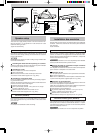
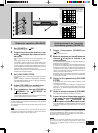
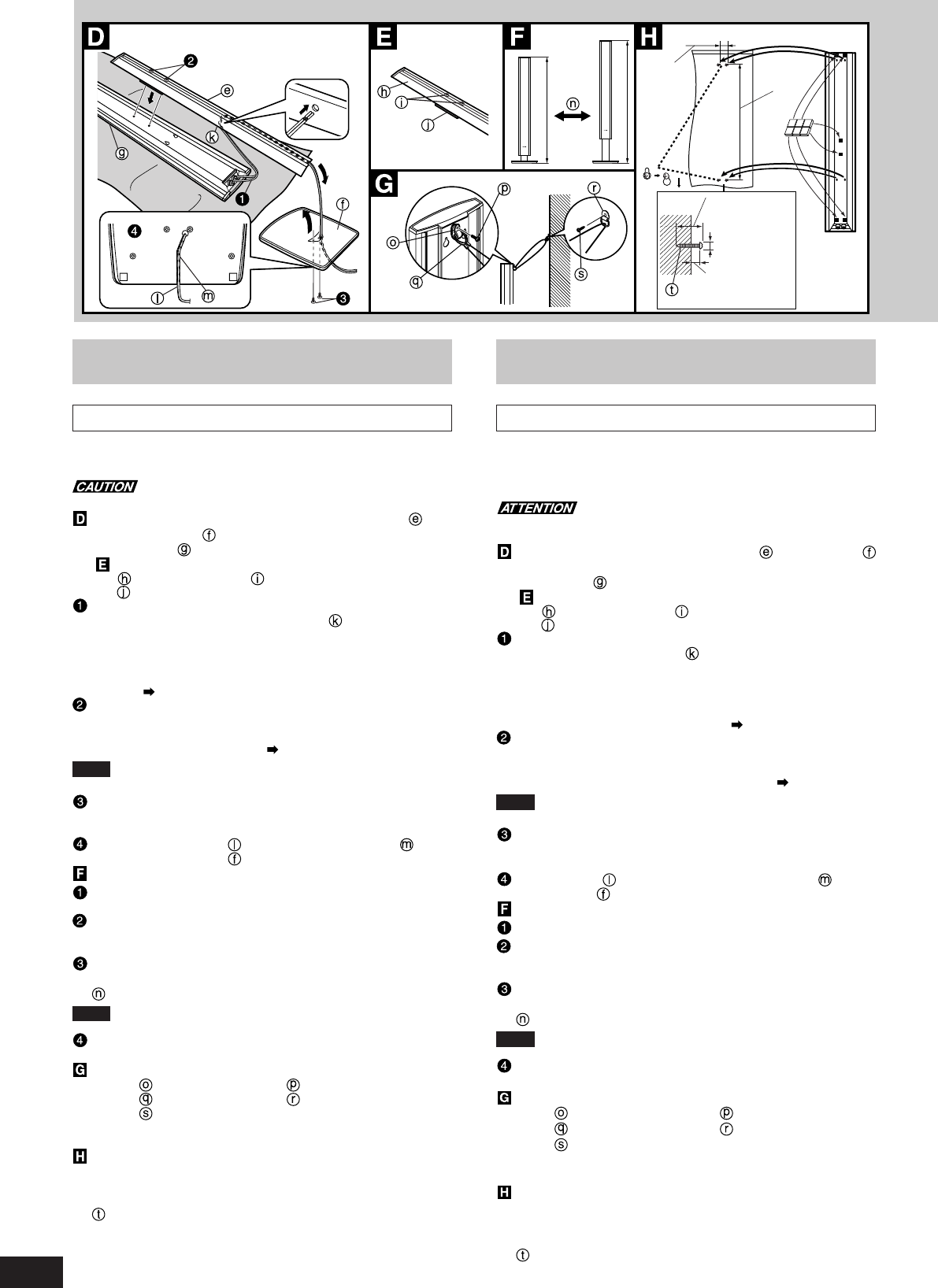
Fixation du stabilisateur assemblé et du socle
(fournis)
Placer l’enceinte face contre le sol.
Vérifier que le stabilisateur assemblé est inclus dans l’emballage.
Stabilisateur Vis de fixation du stabilisateur
Cale
Connecter le câble d’enceinte (inclus) à la borne de l’enceinte
et le faire passer dans le trou du stabilisateur pour l’amener
jusqu’au socle.
•Câble pour enceintes ambiophoniques : environ 10 m (32,8 pi)
Câble pour les enceintes avant : environ 4 m (13,1 pi)
•Pour de plus amples détails sur les connexions des enceintes, se
reporter à la section “Raccordements” ( page 8)
Après avoir décidé de la hauteur de l’enceinte et avoir ajusté
la longueur du câble d’enceinte, fixer le stabilisateur assemblé
à l’enceinte au moyen des deux vis de fixation fournies.
Plage d’ajustement de la hauteur des enceintes ( ci-dessous)
Nota Veiller à ce que le câble ne soit pas coincé entre le
stabilisateur et l’enceinte.
Ajuster la longueur du câble d’enceinte et fixer le socle au
stabilisateur assemblé au moyen des deux vis de fixation
fournies.
Insérer le câble dans la rainure du câble d’enceinte sous le
fond du socle .
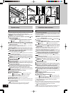
Ajustement de la hauteur
Après l’étape 3 ci-dessus, retirer le câble du côté de l’enceinte.
Desserrer suffisamment les deux vis de fixation du
stabilisateur pour permettre l’ajustement du panneau.
Ne pas trop desserrer les vis ; autrement, l’enceinte pourrait tomber.
Après avoir ajusté la hauteur de l’enceinte et la longueur du
câble, resserrer les deux vis de fixation du stabilisateur.
Plage de réglage : environ 1104 mm à 1390 mm (43 15/32 po à 54 3/4 po)
Nota Veiller à ce que le câble ne soit pas coincé entre le
stabilisateur et l’enceinte.
Faire cheminer le câble dans la rainure sur le socle
(étape 4 ci-dessus)
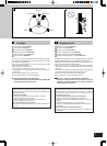
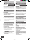
Fixation d’un câble de stabilisation
Exemple Collier en nylon Vis pour collier en nylon
Câble (vendu séparément)
Anneau (vendu séparément)
Vis (vendue séparément)
Insérer une vis à bois dans une section épaisse et résistante du mur.
La paroi murale doit pouvoir supporter plus de 40 kg (88 lb).
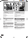
Fixation à un mur
Fixer les quatre pieds en caoutchouc (fournis) sur la paroi arrière de
l’enceinte, en s’assurant que deux font contact avec le mur et deux
sont sur les trous de fixation du stabilisateur assemblé.
Vis (vendue séparément)
Insérer une vis à bois dans une section épaisse et résistante du mur.
La paroi murale doit pouvoir supporter plus de 18 kg (39,6 lb).
30-35 mm
(1-3/16” to 1-3/8”)
(1 3/16 po à 1 3/8 po)
ø7.5-9.5 mm
7-9 mm
(9/32” to 23/64”)
(9/32 po à 23/64 po)
35 mm
(1-3/8”)
(1 3/8 po)
750 mm
(29-35/64”)
(29 35/64 po)
1390 mm
1104 mm
Speaker setup
Front and surround speakers (SB-FS70)
The 4 speakers are the same.
Put the front speakers either side of the television. Put the surround
speakers to the side of or slightly behind the seating area.
Do not attach this speaker to walls or ceilings using methods
other than those described here.
Attaching the assembled stabilizer (included) and
base (included)
Place the speaker facing down.
Confirm you have the Assembled Stabilizer (included).
Stabilizer Stabilizer attachment screws
Spacer
Connect the speaker cable (included) to the speaker termi-
nals and run the cable through the hole on the assembled
stabilizer to the base.
•Speaker cable for the surround speakers : Approx. 10 m (32.8 ft)
For the front speakers: Approx. 4 m (13.1 ft)
•For more information on speaker terminal connections refer to “Con-
nections” ( page 8)
After deciding on the speaker height and adjusting the speaker
cable length, attach the assembled stabilizer to the speaker
using the two stabilizer attachment screws.
Speaker height adjustable range ( below)
Note Do not get the speaker cable caught between the assembled
stabilizer and the speaker.
Adjust the speaker cable length and using the two base at-
tachment screws (included), fasten the base to the assembled
stabilizer.
Insert the speaker cable in the speaker cable groove on the
bottom side of the base .
Adjusting the height
After step 3 indicated above, pull out the speaker cable on the
speaker terminal side.
Loosen the two stabilizer attachment screws enough so that
the panel can be adjusted.
The speaker may fall off if you loosen the screws too much.
After adjusting the speaker height and the length of the cable,
securely fasten the two stabilizer attachment screws.
Adjustable range: Approx. 1104-1390 mm (43-15/32˝ to 54-3/4˝)
Note Do not get the speaker cable caught between the assembled
stabilizer and the speaker.
Fit the speaker cable in the groove in the base.
(Indicated above in step 4)
Attaching a stabilizing wire
Example Nylon clamp Screw for nylon clamp
Wire (not included) Ring (not included)
Screw (not included)
Screw the wood screw into a thick and hard part of the wall.
The surface must be able to support over 40 kg (88 lb.).
Attaching to a wall
Place the rubber pads (included) in four places on the back of the
speaker where it contacts the wall, and on the two attachment holes
for the assembled stabilizer.
Screw (not included)
Screw the wood screw into a thick and hard part of the wall.
The surface must be able to support over 18 kg (39.6 lb.).