


E
N
G
L
I
S
H
16
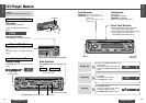
CQ-DP151/DP101W
33
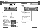
Troubleshooting
E
N
G
L
I
S
H
15
CQ-DP151/DP101W
32
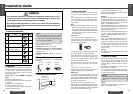
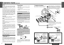
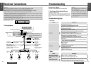
Electrical Connections
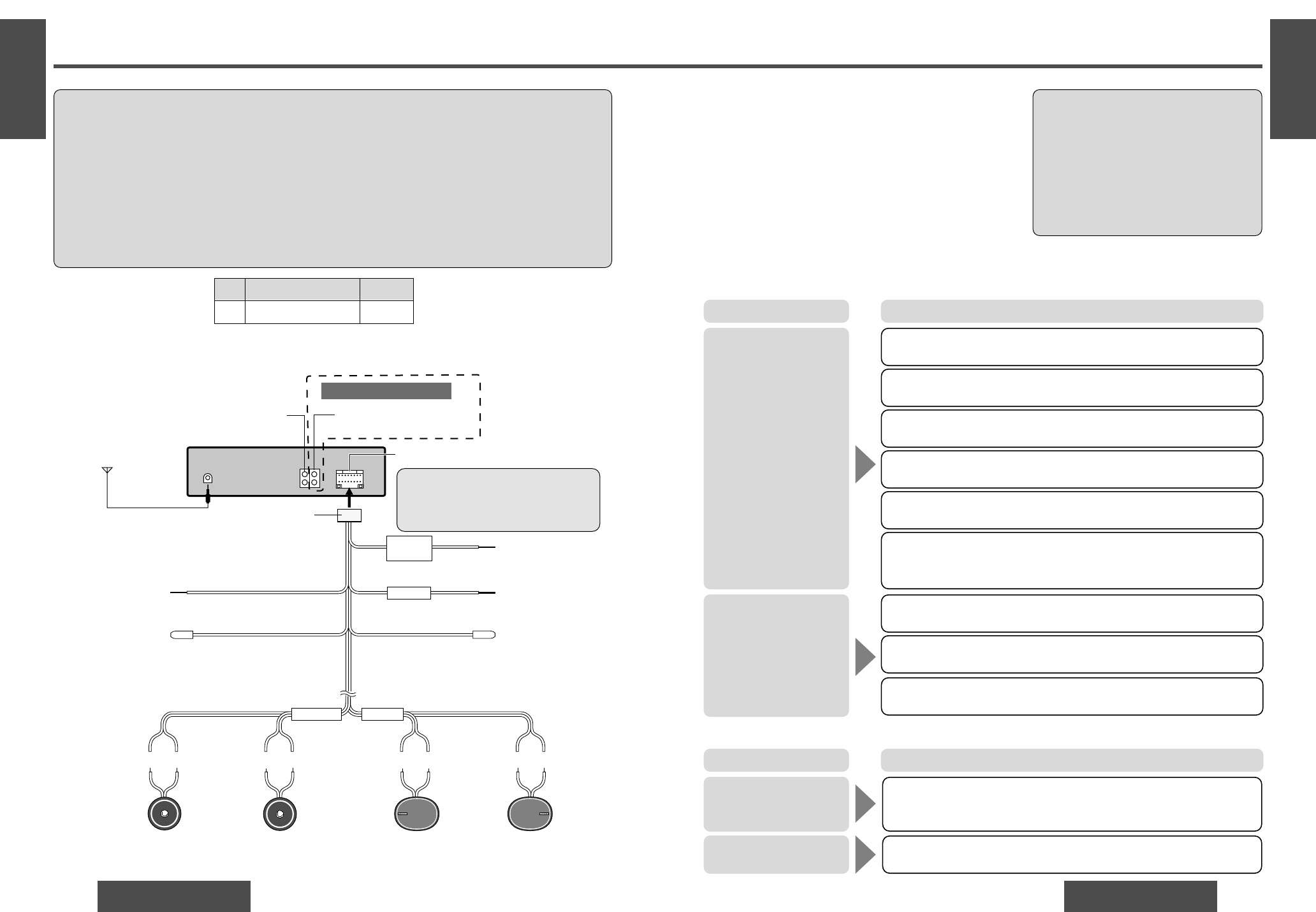
❐ Wiring Diagram
No. Item Q’ty
6 Power connector 1
Power connector
Antenna
6
Yellow
Battery lead
To the car battery,
continuous +12 V DC
Fuse (15 A)
Red
Power lead
To ACC power,
+12 V DC
Dark blue/white stripe
Dark blue
Motor antenna
relay control lead
(To motor antenna) (Max. 500 mA)
This lead is not intended for use with switch
actuated power antenna.
Black
Ground lead
To a clean, bare metallic part of car chassis.
rsrsrs rs
Left speaker
(Front)
Right speaker
(Front)
White Gray Green VioletWhite/black
stripe
Green/black
stripe
Violet/black
stripe
Gray/black
stripe
FRONT SP REAR SP
Left speaker
(Rear)
Right speaker
(Rear)
Speaker lead
Pre-Amp output connector (Front)
Pre-Amp output connector (Rear)
L (White)
R (Red)
Only for CQ-DP151W
CQ-DP151/DP101W
Amp. relay control
power lead
(Max. 500 mA)
This lead is for connection
to the power amplifier.
BATTERY
15A
ACC
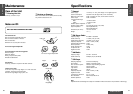
If the fuse (rear panel) blows frequently,
they may be something wrong with the unit.
Consult your nearest Panasonic Servicenter
for service.
§
§
Cautions:
≥This product is designed to operate of a 12 V DC, negative ground battery system.
≥To prevent damage to the unit, be sure to follow the wiring diagram below.
≥Remove approx. 5 mm of protective covering from the ends of the leads before connecting.
≥Do not insert the power connector into the unit until the wiring is completed.
≥Be sure to insulate any exposed wires from a possible short-circuit from the car chassis. Bundle all cables
and keep cable terminals free from touching any metal parts.
≥Remember, if your car has a drive computer or a navigation computer, the data of its memory may be
erased when the battery terminals are disconnected.
≥All other installation methods require the use of dedicated metal fittings. Consult with a qualified servicing
engineer or your dealer if other method are required.
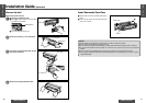
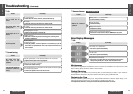
Preliminary Steps
Check and take steps as described in the tables below.
If You Suspect Something Wrong
Immediately switch power off.
Disconnect the power connector and check that there is nei-
ther smoke nor heat from the unit before asking for repairs.
Never try to repair the unit yourself because it is dangerous to
do so.
No power.
Trouble
Car’s engine switch is not on.
➡Turn your car’s ignition switch to ACC or ON.
Troubleshooting Tips
❐ Common
Cables are not correctly connected.
➡Connect cables correctly.
Battery cable is not correctly connected.
➡Connect the battery cable to the terminal that is always live.
Accessory cable is not correctly connected.
➡Connect the accessory cable to your car’s ACC source.
Grounding wire is not correctly connected.
➡Connect the grounding wire to a metal part of the car.
Fuse is burnt.
➡Call the store where you purchased the unit, or your nearest service
station and ask for fuse replacement.
No sound.
Mute is set to ON.
➡Set it to OFF.
Cables are not correctly connected.
➡Connect cables correctly.
Condensation (dew)
➡Wait for a while before use.
Cautions:
≥Do not use the unit if it malfunctions or
is something wrong.
≥Do not use the unit in abnormal condi-
tion, for example, without sound, or
with smoke or foul smell, can cause ig-
nition or electric shock. Immediately
stop using it and call the store where
you purchased it.
Cause/Step
Accessory used for wiring
❐ Radio
Much noise in FM stereo
and monaural broad-
casts.
Station is too far, or signals are too weak.
➡Select other stations of higher signal level.
Battery cable is not correctly connected.
➡Connect the battery cable to the terminal that is always live.
Preset station is reset.
Trouble Cause/Step