


6
Controls & Connectors
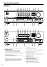
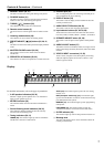
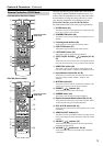
Front Panel
For detailed information, refer to the pages in parenthesis.
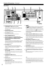
A POWER switch (24)
The North American model doesn’t have this switch.
This is the main power switch. When set to OFF, the
TX-SR501/TX-SR501E is completely shutdown. When set to
ON, the TX-SR501/TX-SR501E is in Standby mode and the
STANDBY indicator lights up.
Don’t turn on the power until you’ve completed, and double
checked all connections (pages 10–23).
Note:
Turning on the TX-SR501/TX-SR501E may cause a momen-
tary power surge that might interfere with other electrical
equipment on the same circuit. If this is a problem, plug the
TX-SR501/TX-SR501E into a different branch circuit.
B STANDBY/ON button (24)
This button is used to set the TX-SR501/TX-SR501E to On or
Standby. For models with a POWER switch, this button has no
effect unless the POWER switch is set to ON.
C STANDBY indicator (24)
This indicator lights up when the TX-SR501/TX-SR501E is in
Standby mode, and it flashes while a signal is being received
from the remote controller.
D DIMMER button (32)
This button is used to adjust the display brightness.
E DIGITAL INPUT button (24)
This button is used to assign the digital inputs.
F SUBWOOFER MODE button (25)
This button is used to select the Subwoofer modes.
STANDBY/ON
PHONES
MASTER VOLUME
VIDEO
2
TAPE TUNER
C
D
VIDEO
3
DVD
AB
SPEAKERS
DIMMER
SURROUND
VIDEO 1
VCR
AUDIO
SELECTOR
DSP
STEREO
STANDBY
DISPLAY
AUDIO ADJUST
SPEAKER ADJUST
FM MODE
SUBWOOFER
MODE
DIGITAL INPUT
MEMORY
DIRECT
S VIDEO AUDIO
VIDEO L R
TUNING
CLEAR
PRESET/ADJUST
VIDEO 3
INPUT
OQR TUSP
234589JKML6
N
7
North American Model
STANDBY/ON
PHONES
MASTER VOLUME
VIDEO
2
TAPE TUNER
C
D
VIDEO
3
DVD
AB
SPEAKERS
DIMMER
SURROUND
VIDEO 1
VCR
AUDIO
SELECTOR
DSP
STEREO
STANDBY
DISPLAY
AUDIO ADJUST
SPEAKER ADJUST
FM MODE
SUBWOOFER
MODE
DIGITAL INPUT
MEMORY
DIRECT
S VIDEO AUDIO
VIDEO L R
TUNING
CLEAR
PRESET/ADJUST
VIDEO 3
INPUT
OQR TUSP
234589JKML6
N
7
OFFON
POWER
1
Other Models