


7
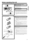
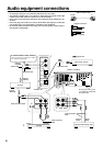
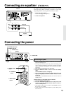
Audio equipment connections
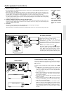
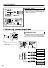
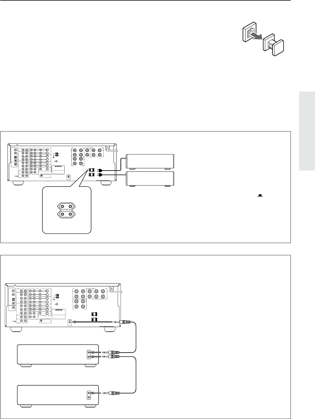
AC outlet connection
You can connect the power cord from another
audio device to the rear of this receiver.
Since the AC outlets on the unit are a
SWITCHED type outlet, you can use the
STANDBY/ON button, to turn on/off the power
to both this receiver and the connected audio de-
vices.
First turn the POWER switch ON (
).
The shape, number, and total capacity of the AC
outlets may differ depending on the area of pur-
chase. Make sure that the total capacity of other
components connected to this unit does not ex-
ceed the capacity that is printed on the rear panel.
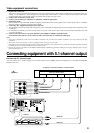
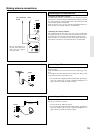
Connections for remote control (z)
You can use the remote controller of this receiver to operate
cassette tape decks and compact disc players that have Onkyo
z connectors.
Connect a remote control cable to the connector with the z
mark.
• An z remote control cable equipped with a 3.5mm (1/8
in.)-diameter miniature two-conductor phone plug comes
with every compact disc player or cassette tape deck that
has an z connector.
• Remote control operation is not possible if only the remote
control cable is connected – the audio connection cables
must also be connected.
• This receiver’s remote controller does not support control
of Onkyo turntables.
• If the connecting device has two z connectors lined-up
vertically or horizontally, you can use either of them. They
both offer the same functionality.
• You can use the remote controller for the TX-DS777/TX-
DS676 to control a Onkyo DVD player or MD recorder
that is not connected via an z cable. When you control
such a DVD player or MD recorder, point the remote con-
troller toward the sensor area of the DVD player or MD
recorder.
R
V
L
R
L
R
L
R
L
R
L
VIDEO-1
OUT
IN
VIDEO-2
VIDEO-3
OUT
IN
IN
TAPE
VIDEO
S VIDEO
OSD SELECTOR
(REC)
OUT
IN
(PLAY)
DIGITAL OUTPUT
DIGITAL INPUT
COAXIAL
1
COAXIAL
2
OPTICAL
1
OPTICAL
2
OPTICAL
FRONT
FRONT
CENTER
SUB
WOOFER
SURROUND
FRONT
CENTER
CD
PHONO
SUB
WOOFER
SURROUND
AMP IN
PRE OUT
GMD
MONITOR
OUT
S
V
S
REMOTE
CONTROL
IN
DVD
LRLR
LR
SURROUND SPEAKERS
FRONT SPEAKERS A
CENTER
SPEAKER
FRONT SPEAKERS B
MULTI CHANNEL
INPUT
AV RECEIVER
CAUTION: SPEAKER IMPEDANCE
6 OHMS MIN. / SPEAKER
ANTENNA
AM
FM
75
AC OUTLETS
AC 120V 60Hz
SWITCHED
TOTAL 120W 1A MAX.
MODEL NO.
TX-DS777
Capacity is total
120 watts.
U.S.A. and
Canadian models
Worldwide and
European models
Capacity is total
100 watts.
R
V
L
R
L
R
L
R
L
R
L
VIDEO-1
OUT
IN
VIDEO-2
VIDEO-3
OUT
IN
IN
TAPE
VIDEO
S VIDEO
OSD SELECTOR
(REC)
OUT
IN
(PLAY)
DIGITAL OUTPUT
DIGITAL INPUT
COAXIAL
1
COAXIAL
2
OPTICAL
1
OPTICAL
2
OPTICAL
FRONT
FRONT
CENTER
SUB
WOOFER
SURROUND
FRONT
CENTER
CD
PHONO
SUB
WOOFER
SURROUND
AMP IN
PRE OUT
GMD
MONITOR
OUT
S
V
S
REMOTE
CONTROL
IN
DVD
LRLR
LR
SURROUND SPEAKERS
FRONT SPEAKERS A
CENTER
SPEAKER
FRONT SPEAKERS B
MULTI CHANNEL
INPUT
AV RECEIVER
CAUTION: SPEAKER IMPEDANCE
6 OHMS MIN. / SPEAKER
ANTENNA
AM
FM
75
AC OUTLETS
AC 120V 60Hz
SWITCHED
TOTAL 120W 1A MAX.
MODEL NO.
TX-DS777
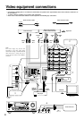
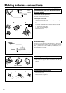
CD Player
TX-DS777/TX-DS676
Cassette Tape Deck
1. DIGITAL INPUT connectors
• If your CD player has a digital output connector, connect it to a proper DIGITAL INPUT connector for
clear and dynamic sound play.
• This unit provides four digital input connectors to connect CD players, MD recorders, DAT decks, etc.
having a digital output connector. When using these connectors, connect the unit also via the audio con-
nection cables. You should also note that the signals you can record are analog signals only.
• The digital inputs, COAXIAL 1, 2 and OPTICAL 1, 2can be assigned to individual input selector buttons,
so when an input selector button is pressed, the assigned digital input is used instead of the corresponding
analog input. (See page 23,29.)
2. OPTICAL DIGITAL OUTPUT connector (TX-DS777 only)
If you have a digital recorder, such as an MD recorder, DAT, and CD-R (Compact Disc Recorder), con-
nect the recorder’s digital input connector to this connector. In this case, always use commercially avail-
able optical digital audio cables.
3. Turntable
This receiver is designed for use with turntables using moving magnet cartridges.
Connect a ground (or earth) wire to GND terminal.
With some players, connecting a ground wire results in larger noise. If so, do not connect any ground wire.
Remove the protective
caps before making
connections. When not in
use, be sure to replace
them.
Optical digital connector