


20
Connections
INPUT 1
INPUT 2
OUTPUT
COMPONENT VIDEO
Y
OPTICAL
1
2
IN
IN
IN
IN
FRONT
SURR
CENTE
R
SUB
WOOFE
R
VIDEO 2
VIDEO 1
VIDEO 2
DVD
MONITOR
OUT
DVD
TAPE
IN
L
R
VIDEO 3
VIDEO 1
V
VIDEO 3
OPTICAL
IN
IN
IN
ININ
IN
OUTOUT
OUTOUTOUT
S
DIGITAL
OUT
CD
COAXIAL
L
R
IN
GND
PHONO
COAXIAL
PR
PB
ZO
N
ANTENNA
FM
75
AM
REMOT
E
CONTR
O
R
L
ZONE 2
LINE OUT
(MONITOR OUT)
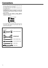
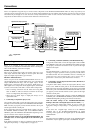
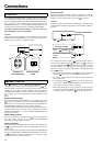
8. TV monitor or projector
: Signal flow
L (white)
R (red)
L (white)
R (red)
S Video output
Video output
Video input
S Video input
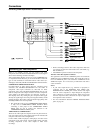
7. DVD recorder, other
digital video recording
device (VIDEO 2)
Digital audio
input (coaxial)
Video input
S Video input
Analog audio
input
Analog audio
output
Component
video input
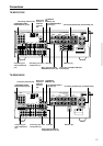
TX-SR701/701E only
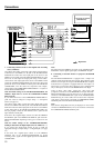
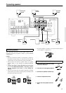
7. Connecting a DVD recorder or other digital video recording
device (VIDEO 2)
Using RCA video cables, connect the video output jack (composite)
of the device to the VIDEO 2 V IN jack of the TX-SR701/701E/
601/601E and connect the video input jack of the device to the
VIDEO 2 V OUT jack of the TX-SR701/701E/601/601E. Or if the
device has S video input and output jacks, using S video cables,
connect the S video output jack of the device to the VIDEO 2 S IN
jack of the TX-SR701/701E/601/601E and connect the video input
jack of the device to the VIDEO 2 S OUT jack of the TX-SR701/
701E/601/601E. Or if the device has component video outputs,
connect them to the COMPONENT VIDEO INPUT 1 or 2 jacks on
the TX-SR701/701E/601/601E.
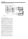
With the initial settings of the TX-SR701/701E/601/601E, the
VIDEO 2 input source is set for the COMPONENT VIDEO
INPUT 2 jacks.
If you connect the device to the COMPONENT VIDEO INPUT 1
jacks, this must be changed at “Input Setup” → “Component
Video” (see page 53).
Using RCA audio cables, connect the audio output jacks of the
device to the VIDEO 2 IN audio jacks of the TX-SR701/701E/601/
601E and connect the audio input jacks of the device to the VIDEO
2 OUT audio jacks of the TX-SR701/701E/601/601E. Make sure
that you properly connect the left channels to the L jacks and the
right channels to the R jacks.
If the device has a digital output, connect it to either the DIGITAL
IN COAXIAL jack or the DIGITAL IN OPTICAL jack of the TX-
SR701/701E/601/601E depending on the type of connector on the
device.
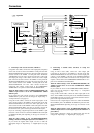
With the initial settings of the TX-SR701/701E/601/601E,
nothing is allocated as the digital input source for VIDEO 2 (----).
If you connect the digital audio output, be sure to make the
appropriate changes at “Input Setup” → “Digital Input” (see page
52).
If the device has a digital input, connect it to the DIGITAL
OUTPUT jack of the TX-SR701/701E/601/601E for digital
recording of the signal from the digital input of the TX-SR701/
701E/601/601E.
Note:
The output from the DIGITAL OUT jack of the TX-SR701/701E/
601/601E is only the digital signal input to the DIGITAL IN jack.
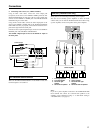
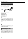
8. Connecting a television monitor or projector (MONITOR
OUT)
The TX-SR701/701E/601/601E is equipped with a simple Y/C
separate circuit and simple Y/C mixed circuit. Since both the signal
from the S and V inputs are output to the MONITOR OUT S output,
if the television or projector is equipped with an S video input, it is
unnecessary to connect the video connectors. If it is equipped with
only a video input, connect it to the MONITOR OUT V output.
Using an RCA video cable, connect the video input jack
(composite) of the device to the MONITOR OUT V jack of the TX-
SR701/701E/601/601E. Or if the device has an S video input jack,
connect it to the MONITOR OUT S jack of the TX-SR701/701E/
601/601E using an S video cable. Or if the device has component
video inputs, connect them to the bank of COMPONENT VIDEO
OUTPUT jacks on the TX-SR701/701E/601/601E.
Note:
Note that the Setup Menu will only be displayed on the monitor
connected to MONITOR OUT (S or V) and not those connected to
the COMPONENT VIDEO OUTPUT jacks.