


11
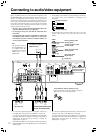
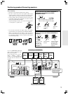
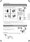
DVD player or component
with 5.1 ch output (DVD)
Video cassette player,
Satellite tuner, LD
player* etc. (VIDEO 2)
VCR (VIDEO 1)
Audio/video
connection cable
S video cable (S
video signal)
Video
Audio (L)
Audio (R)
Signal flow
S video plug
Coaxial cable
(Digital signal)
Coaxial plug
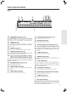
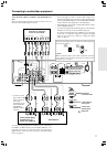
About the DVD, VIDEO 1, VIDEO 2 and MONITOR OUT
jacks
The video input/output connections are also necessary even if you
make the S video input/output connections.
Connecting to audio/video equipment
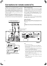
REMOTE
CONTROL
R
L
R
L
R
L
IN
IN
IN
COAXIAL
OPTICAL
12
IN
IN
IN
IN
FRONT
SURR
CENTER
SUB
WOOFER
VIDEO 2
VIDEO 1
OUT
OUT
OUT
DIGITAL INPUT
VIDEO 2
VIDEO 1
DVD MONITOR
OUT
VIDEO
S VIDEO
DVD
TAPE
CD
FRONT
SPEAKERS A
FRONT
SPEAKERS B
SURROUND
SPEAKERS
CENTER
SPEAKER
L
R
L
R
AC OUTLET
ANTENNA
FM
75
AM
SUBWOOFER
PRE OUT
DIGITAL
OUT
S VIDEO
OUT
S VIDEO
IN
S VIDEO
OUT
VIDEO
OUT
AUDIO
OUT
VIDEO
IN
AUDIO
IN
RL RLLR
LR
VIDEO
OUT
AUDIO
OUT
S VIDEO
OUT
VIDEO
OUT
FRONT
CENTER
SUBWOOFER
SURR
LR
AUDIO OUT
COAXIAL
•
If the DVD player has both 5.1 channel audio outputs and 2
channel audio outputs, and you want to connect the DVD player
only using the FRONT L/R jacks on the TX-SR500/TX-SR500E,
use the 2 channel audio output jacks on the DVD player.
• If the DVD player only has the 2 channel audio outputs, connect
it to the FRONT L/R jacks.
• To connect the digital output from DVD player connected to the
DVD jacks to this unit, use the COAXIAL input jack.
To connect the digital output to the OPTICAL 1 or 2 input jack
of this unit, it is required to change the assignment of digital
inputs to input sources by referring to “Setting the digital
inputs” on page 22.
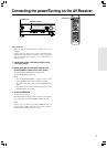
Audio (L)
Video
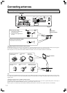
The shape and capacity of the AC outlet may differ depending
on the area of purchase.
To connect the digital output from satellite tuner etc. connected to
the VIDEO 1 or VIDEO 2 jacks to the COAXIAL, OPTICAL 1 or 2
input jack of this unit, it is required to change the assignment of
digital inputs to input sources by referring to “Setting the digital
inputs” on page 22.
DO NOT connect the
power cord (mailns
lead) at this time.
Caution
Make sure that the capacity of the other components connected
to this unit does not exceed the capacity that is printed on the
rear panel (e.g., 120 watts).
AC OUTLET
AC 120
V 60
Hz
SWITCHED
120
W 1
A
MAX.
SWITCHED
100W MAX.
AC 230-240
V
50
Hz
AC OUTLET
or etc
*
If you have an LD
player with AC-3RF
output, connect via
an AC-3RF
demodulator to one
of the TX-SR500/
TX-SR500E’s
DIGITAL INPUT
terminals.