


11
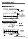
Rear panel facilities and connections
Note:
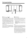
• Do not change the INPUT SELECT switch setting
when the RDA-7.1 is turned on.
• Make sure that connections have been made only to the
inputs selected with the INPUT SELECT switches and
nothing is connected to the other ones.
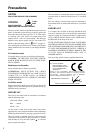
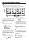
+ OUTPUT – (Speaker output)
(Binding post)
The RDA-7.1 is equipped with high-current binding posts
for use at output terminals to the speaker system. To
obtain the best in sound quality from the RDA-7.1, we
recommend the use of high-quality speaker cables.
For each channel, connect the negative output post to the
negative input terminal of the speaker and the positive
output post to the positive input terminal of the speaker.
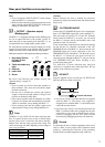
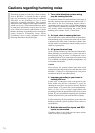
Make the connections following the procedure given below.
1. Strip away 5/8 inch
(15 mm) of wire
insulation.
2. Twist wire ends very
tight.
3. Unscrew
4. Insert wire
5. Screw
Be sure to read “Phasing your speaker system” and
“Speaker ratings” on page 12.
Caution
• Do not connect any devices other than speakers to
these terminals. Also, never short-circuit the output
from these terminals.
• Be sure not to mistake the positive and negative
outputs or the left and right speakers. Doing so will
result in an unnatural sound space.
• Only connect speakers with an impedance of 4 ohms
or greater. If a speaker with an impedance of less than
4 ohms is connected, it may damage the RDA-7.1.
• Do not connect more than one speaker cable to one
output terminal. Doing so may damage the RDA-7.1.
Fuse
The RDA-7.1 uses a 250V AC slow-blow (time lag) main
fuse. To replace the fuse, insert a coin or similar object
into the groove, turn it to the left, and remove the fuse.
Replace only with the same type and same rating. The
correct fuse rating will differ depending on the voltage of
your set as given here.
Power Supply Fuse Rating
120V 15A/250V
220V/230V/240V T10A L/250V
Warning
Before replacing the fuse or making any electrical
connections, always turn off the Power and disconnect the
Power cord.
12V TRIGGER IN/OUT
Connect the 12V TRIGGER IN jack to AV controller that
have a 12V TRIGGER output jack, such as the RDC-7.1.
This jack works on between 5 to 12 volts DC. With the
Power switch of the RDA-7.1 set to On, you can switch
the RDA-7.1 between the On and Standby states with
operations at the AV controller.
If you want another component to be activated by turning
on and off the AV controller connected to the 12V
TRIGGER IN jack of the RDA-7.1, then connect the 12V
TRIGGER input jack of that component to the 12V
TRIGGER OUT jack of the RDA-7.1. In this state, even if
the RDA-7.1 is turned off, the signal from the AV
controller passes through the RDA-7.1 and goes out the
12V TRIGGER OUT jack. Daisy chaining is also
possible using these jacks.
Use φ1/8-inch (3.5-mm) monaural-type mini-jack
connectors or supplied stereo mini-plug cable. The tip
polarity of the connector is positive.
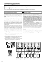
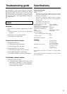
AC INLET
Plug the supplied Power cord into this AC INLET and
then into the Power outlet on the wall,
• Do not use a Power cord other than the one supplied
with the RDA-7.1. The Power cord supplied is
designed for use with the RDA-7.1 and should not be
used with any other device.
• Never have the Power cord disconnected from the
RDA-7.1 while the other end is plugged into the wall
outlet. Doing so may cause an electric shock. Always
connect by plugging into the wall outlet last and
disconnect by unplugging from the wall outlet first.
Ground
If connecting the unit to another equipment causes noise
such as a hum, you may improve the reproduced sound
quality by connecting this terminal to the grounding
terminal of the connected equipment with a lead wire.
12
5/8 inch
(15 mm)
34 5
Power cord (supplied)
To an AC wall outlet
AC INLET