


8
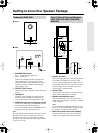
Connecting the Speakers
Read the following before connecting your speakers:
•Turn off your amp before making any connections.
• The nominal impedance of these speakers is 8
Ω
. Use
only an amp that supports this impedance.
•Pay close attention to speaker wiring polarity. Connect
positive (+) terminals to only positive (+) terminals,
and negative (–) terminals to only negative (–) termi-
nals. If the speakers are wired incorrectly, the sound
will be out of phase and will sound unnatural.
• Be careful not to short the posi-
tive and negative wires. Doing so
may damage your amp.
Tip:
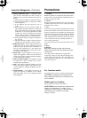
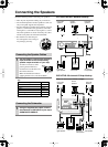
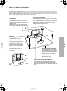
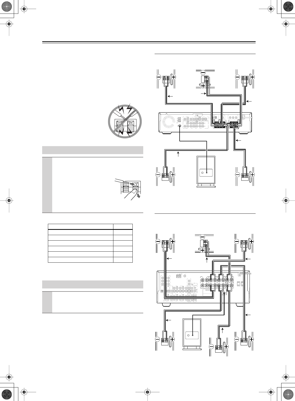
HTP-240 & DR-S2.2 Receiver Hookup
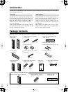
SKS-HT240 & 6-channel AV Amp Hookup
Onkyo AV receiver used in this example.
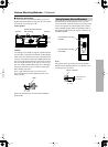
Connecting the Speaker Cables
1
Use the cables to connect each speaker’s
input terminals to the corresponding
speaker output terminals on your amp.
To make a connection, while
pressing the terminal lever,
insert the wire into the hole, and
then release the lever.
Make sure that the terminals are
gripping the bare wires, not the insulation.
Speaker terminal (+) Color
Front left White
Front right Red
Center Green
Surround left Blue
Surround right Gray
Surround back (SKS-HT240 only) Brown
Connecting the Subwoofer
1
Using the supplied RCA cable, connect
the subwoofer’s LINE INPUT to your amp’s
SUBWOOFER PREOUT.
REMOTE
CONTROL
OUT
2 ––VIDEO –– 1 VIDEO 2 VIDEO 1
IN
IN IN
IN
OUT
OUT
IN OUT IN
IN
IN
VIDEO2
CDR/PC
VIDEO 1 TAPE
MD/HD
TV/LINE
MON
OUT
MON
OUT
L
R
VIDEO
S VIDEO
AUDIO
SUB
WOOFER
PRE OUT
AUDIO
FM
75
ANTENNA
DIGITAL
OUTPUT
DIGITAL INPUT
VIDEO 2 VIDEO 1
OPT
OPT
COAX
AM
Y
P
B
P
R
COMPONENT VIDEO OUTPUT
CENTER
SPEAKER
SURROUND
SPEAKERS
R
L
R
L
R
BA
L
FRONT SPEAKERS
LINE
INPUT
Front right
speaker
Center
speaker
Front left
speaker
Surround
right speaker
Powered
subwoofer
Surround
left speaker
Red
Green
White
Blue
Gray
INPUT 1
INPUT 2
OUTPUT
COMPONENT VIDEO
P
R
PB
Y
COAXIAL
OPTICAL
1
2
IN
IN
IN
IN
FRONT
SURR
CENTER
SUB
WOOFER
VIDEO 2
VIDEO 1
VIDEO 2
DVD
DVD
TAP E
CD
TAP E
CD
L
R
L
R
VIDEO 3
VIDEO 1
V
12
V
TRIGGER
OUT
ZONE 2
VIDEO 3
OPTICAL
IN
IN
IN
INININ
IN
OUTOUT
OUTOUTOUT
S
IR IN
DIGITAL
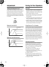
CAUTION: SPEAKER IMPEDANCE
6 OHMS MIN. /SPEAKER
FRONT
SPEAKERS
ZONE
2
SPEAKERS
SURROUND
SPEAKERS
CENTER
SPEAKER
SUBWOOFER
12
V
TRIGGER
OUT
R
L
R
L
ANTENNA
FM
75
AM
OUT
AC OUTLETS
AV RECEIVER
MODEL NO. TX
-
SR
601
SURROUND BACK
SPEAKER
PRE OUT
MONITOR
OUT
REMOTE
CONTROL
R
L
ZONE 2
LINE OUT
AC 120
V 60
Hz
SWITCHED
TOTAL 120W 1A MAX.
LINE
INPUT
Front right
speaker
Center
speaker
Front left
speaker
Surround
right speaker
Powered
subwoofer
Surround
left speaker
Surround
back speaker
Red Green White
Blue
Brown
Gray