


-5-
pH
units.
112
in place.
The output is adjustable
for a span of 2
to
6
fl
and
#2
is with jumpers
pH
point of the range.
The adjustments are
sensitive and interactive,
do not attempt large changes, work both ad-
justments in turn with small changes.
RANGE
mA
point at the highest
20
pH
point of the range, and the "Span" sets the
mA
point at the lowest
pH,
the "Zero" adjust sets for the 4
pH
units,
for spans of less than 14
#l
in place.
The PHTX-11 is shipped with this
jumper in place.
The output is adjustable for a span of 6 to 14
i/l
is with Jumper
"SloPe"
for a reading of 14.00.
until
Output ranging
is accomplished with the jumpers described in Section
1.7, they are used in conjunction with the Span and Zero adjustments.
RANGE
Ad,just
pH
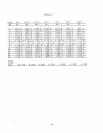
Simulator.
Refer to Table I for the millivolt equivalent if a
millivolt source is used.
pH
on the
"14"
pH
Simulator.
Adjust the pot
the display reads 7.00.
"SLOPE"
adjustment is made with the input at
"7"
on the
pH
of
CAL"
adjustment is made with the input at zero volts from the
millivolt source or a
"pH
2OmA).
Remove the cover from the range switch and turn all switches "Off".
#l>.
Input adjustments should not be made while
the-output is in an-over current condition (ie:
greater than
(25'C
compensation).
Refer to Table I for resistance values and
input millivolt values for other temperatures.
Before making any adjustments,
the output jumper should be in the full
range position (Range
8.66K
resistor
for manual temperature compensation at the terminals with the resistor
symbol
pH
Simulator or a
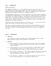
2.2 Precision digital
2.3 D.C. power supply
2.4 Load resistor 250
Calibration Procedure
3. 1
3. 2
3. 3
3. 4
3. 5
millivolt source.
multimeter.
24 to 30 volts.
ohm or 500 ohm.
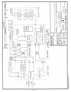
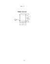
Connect the equipment
as shown in block diagram.
Use an
-
CALIBRATION
The recommended calibration interval
for the transmitter is six months under
normal operating conditions,
and assuming the sensor is in good condition.
This system may need adjustment to compensate for reduced efficiency of the
sensor before the calibration interval.
Equipment Required
2.1
mA
and the decimal point should shift one place to the right.
PART IV
2.3 Test the display
by pressing the display switch.
The display should
indicate