4/s
5/6
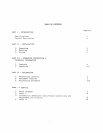
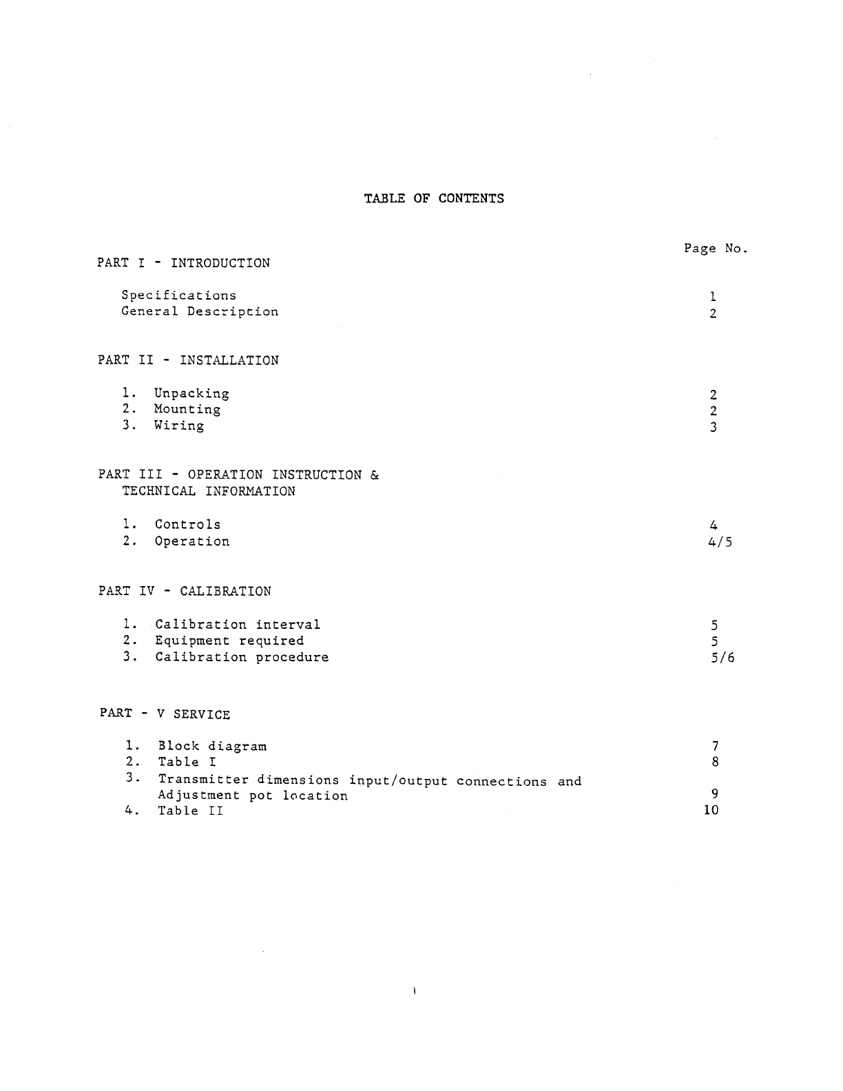
PART
V SERVICE
1.
2.
3.
4.
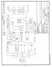
Block diagram
7
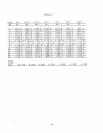
Table I
8
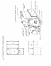
Transmitter dimensions input/output connections and
Adjustment pot location
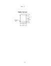
Table II
9
10
1
2
2
2
3
4
-
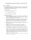
CALIBRATION
1.
Calibration interval
5
2.
Equipment required
5
3.
Calibration procedure
&
TECHNICAL INFORMATION
1.
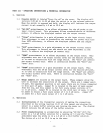
Controls
2.
Operation
PART IV
-
OPERATION INSTRUCTION
-
INSTALLATION
1.
Unpacking
2.
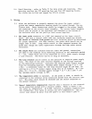
Mounting
3.
Wiring
PART III
-
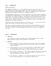
INTRODUCTION
Specification s
General Descriptio n
PART II
TABLE OF CONTENTS
Page No.
PART I


