Page 12
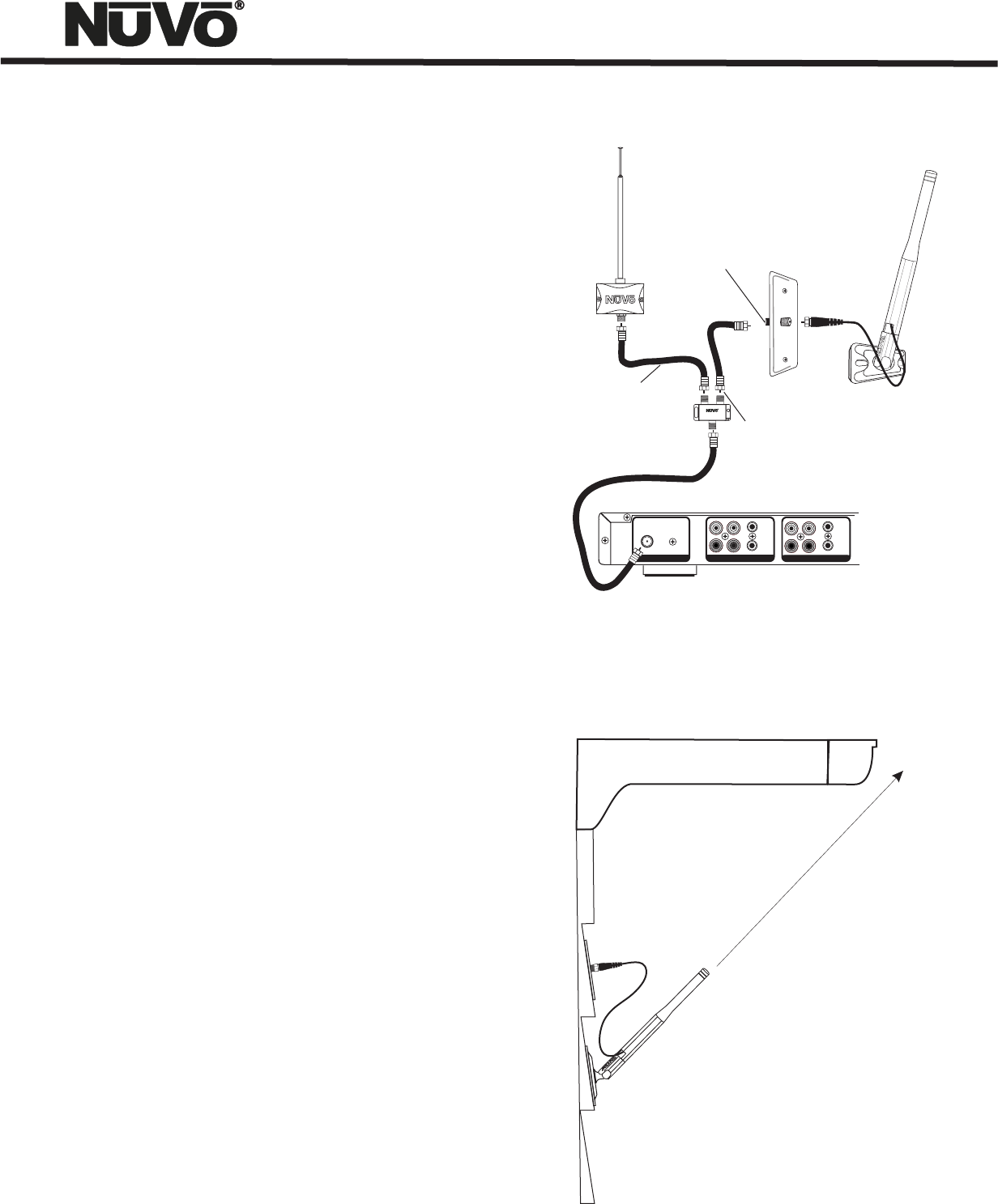
Proper Location of the XM Antenna
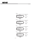
Location of the XM antenna is critical to proper performance.
There cannot be any obstructions between the antenna and the
southern sky. This means that any possible interference from
buildings, trees or other structures must be avoided.
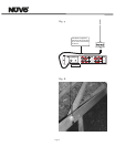
The most common location is mounted to the eve of the home’s
exterior. If you are using the eve as the location of the
antenna, be careful to locate it low enough that the roof over
hang does not obstruct the antenna from clear sky, fig. 10. Any
outside location will suffice. For best performance, the
antenna should be mounted vertically, and placed at
approximately a 45° angle. Again, see fig. 10. This angle is
closer to 50°or 60° if you are in the extreme southern portion
of the United States.
Subscribing to the XM Service
XM satellite radio provides 100 channels of music, news,
sports, comedy, talk, and entertainment. Each of the T2 XM
tuner modules require a subscription from XM. Listeners can
subscribe by visiting XM on the Web at www.xmradio.com or by
calling Xm’s Listener Care at (800)852-9696. Have the Radio
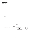
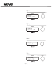
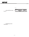
ID ready. This is found by tuning to channel 0 on the tuner, on
the tuner’s back panel or on the packaging.
Please note that XM service is not available in Alaska or Hawaii.
Warning Against Reverse Engineering
It is prohibited to copy, decompile, disassemble, reverse
engineer, or manipulate any technology incorporated in
receivers compatible with the XM Satellite Radio system.
Furthermore, the AMBE (R) voice compression software
included in this product is protected by intellectual property
rights including patent rights, copyrights, and trade secrets of
Digital Voice Systems, Inc. The user of this or any other
software contained in an XM Radio is explicitly prohibited from
attempting to copy, decompile, reverse engineer, or
disassemble the object code, or in any other way convert the
object code into human-readable form. The software is
licensed solely for use within this product.
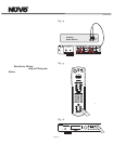
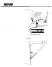
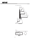
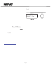
Fig . 9
Fig . 10
L
L
OUTAUX IN
AUX IN
R
R
TRIGGER
ON=+12V
AUDIO
OUTPUT
TUNER B TUNER A
AUDIO OUT
AUDIO
OUTPUT
ANTENNA INPUT
IN
USE ONLY NuVo
NV-T2PAS
POWERED ANTENNA SYSTEM
TRIGGER
ON=+12V
AM/FM
ANTENNA IN
XM
ANTENNA IN
COMBINED
ANTENNA OUT
NV-T2FXC SINGNAL
COMBINER
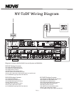
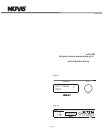
For XM reception the RG6 cable
between the tuner, signal combiner,
and XM antenna must be within
120ft.
Use any commercially
available barrel connector or
connection plate as shown
in the diagram.
The connection
to the AM/FM
antenna can be
up to 200 ft.
NV-T2FX Dual AM/FM/
Weather Band and XM
For XM cable distances less than
80 feet use the included NV-PPFM6
signal attentuator.


