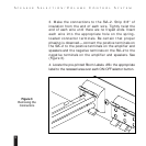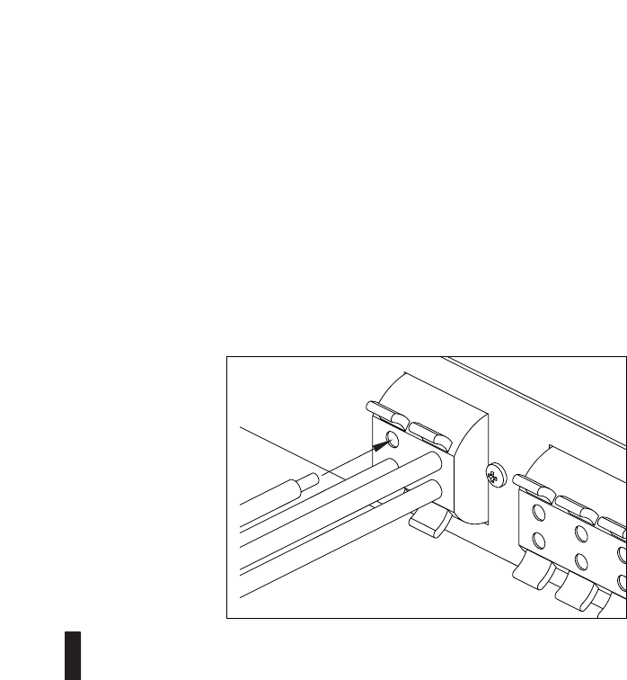
3. Make the connections to the SVL-2. Strip 3/8" of
insulation from the end of each wire. Tightly twist the
end of each wire until there are no frayed ends. Insert
each wire into the appropriate hole on the spring-
loaded connector terminals. Be certain that proper
phasing is observed—connect the positive terminals on
the SVL-2 to the positive terminals on the amplifier and
speakers and the negative terminals on the SVL-2 to the
negative terminals on the amplifier and speakers. See
(Figure 3).
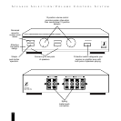
4. Locate the pre-printed Room Labels. Affix the appropriate
label to the recessed area over each ON/OFF selector button.
9
S
PEAKER
S
ELECTION
/V
OLUME
C
ONTROL
S
YSTEM
Figure3
Removing the
Connectors


