


Try to line the holes up perfectly, because
it makes pulling the wire much easier. A
good technique is to snap a chalk line
across the face of the studs or against the
bottom of the ceiling joists. Then work
backward so that you can always see the
holes you have already drilled. Paying
careful attention to this will save you a lot
of time later on!
Pulling the Cable
Pull the cable in sections (from the stereo
to the volume control, from the volume
control to the speaker). Start with the
longest sections and use left over wire to
complete the short sections. If you plan to
pull many rooms at the same time through
a central route, walk off the distance to
each destination, add a generous fudge
factor for turns and other obstacles, then
cut off each section so that you have a
bundle of wires you can pull at once.
Whenever you run the wire further than
four and one half feet from a hole in a stud
or joist (open attic space, going up walls,
etc.), fasten the wire to the joists or studs
using cable clamps or appropriately sized
wire staples. The wire should not have
large sags in it, nor should it be too tight.
Try to protect the wire from being stepped
on in attics or other unfinished crawl
spaces. There are guard strips, raceways
and conduits which can be used to protect
the cable. Consult the local building code
for special requirements in your area.
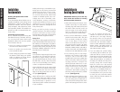
Concealing Speaker Wire
in Existing Walls
This is actually a fairly simple task if you
restrict your choice of speaker locations
and wire routes to the interior walls or
ceilings of your home. Interior walls in
almost all North American residences are
hollow, so that it is easy to flush mount
speakers into them and route new speaker
cable around the house. What you see
when you look at the painted wall board,
plaster, or paneling is only the skin of the
wall. Behind the skin is the skeleton; two-
by-four wood or metal “studs” running
vertically from the floor to the ceiling in
walls and two-by-six or larger “joists” run-
ning horizontally in the ceilings and
floors. In between the studs and the joists
is the space for the wiring and plumbing
of your home.
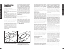
Exterior walls are different. They must
insulate the house from the heat and cold
outside, so they are stuffed with insulation.
The national building code requires that
the hollow wall space in exterior walls be
broken by a horizontal stud placed
between the vertical studs. This “fire
blocking” makes it very difficult to retrofit
long lengths of wire. In some areas of the
country the exterior walls are constructed
of solid masonry, and have no hollow
space for speakers or wires.
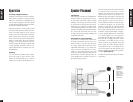
Start by examining all the possible routes
you might take to run the speaker wire
from the speaker to the volume control
and back to the stereo. Use a stud sensor
or other device to locate the internal struc-
ture of the wall. You want to avoid all
studs or joists. A typical route would be:
from the speaker location in the ceiling,
across the attic, then down through a top
plate (the horizontal 2x4 or 2x6 laid
across the vertical studs) to the volume
control location, back up to the attic,
across the attic, and finally down another
wall plate to a J-Box in the wall behind the
stereo system itself (See Figure 8).
Identify where all of your electrical,
phone, and TV wiring is likely to be and
plan to route around it all. You can acci-
dentally induce 60Hz hum on your speak-
ers if you run your speaker wire right
beside electrical wire for more than a few
feet. Try to keep speaker wire running par-
10
Installation Fundamentals
Installation in New
Construction
Insulating the Wall Cavity
If feasible, fill the wall cavity with insula-
tion at this point.
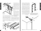
Mounting The New Construction
Bracket
The hole saving bracket enables a faster
and cleaner final installation of the speak-
er. It forces the drywall installer to cut out
the speaker hole for you and provides
wire ties for the speaker wire, reducing the
risks of accidental loss or movement of the
wire. In addition, it enables you to align
your speakers with other ceiling fixtures
with great accuracy since you can really
see exactly where the speaker will be.
To install the bracket, first attach the
QuickSnap
™
new construction wings to
the bracket by snapping them into the
sides of the bracket. The wings can be
shortened by breaking them along the
scored lines if the length will interfere with
corner or eaves.
The wings and brackets have centering
lines to simplify placement of the speakers.
Screw one side of the assembled bracket
with wings to the joist using one of the
supplied screws. Level the bracket. Screw
the other side of the bracket/wing assem-
bly to the joist. Two screws on each side
make for a very secure installation. Secure
the wire to the bracket using bracket’s
wire tie. The drywall installers will cut the
drywall to the exact size of the bracket.
(SeeFigure 12)
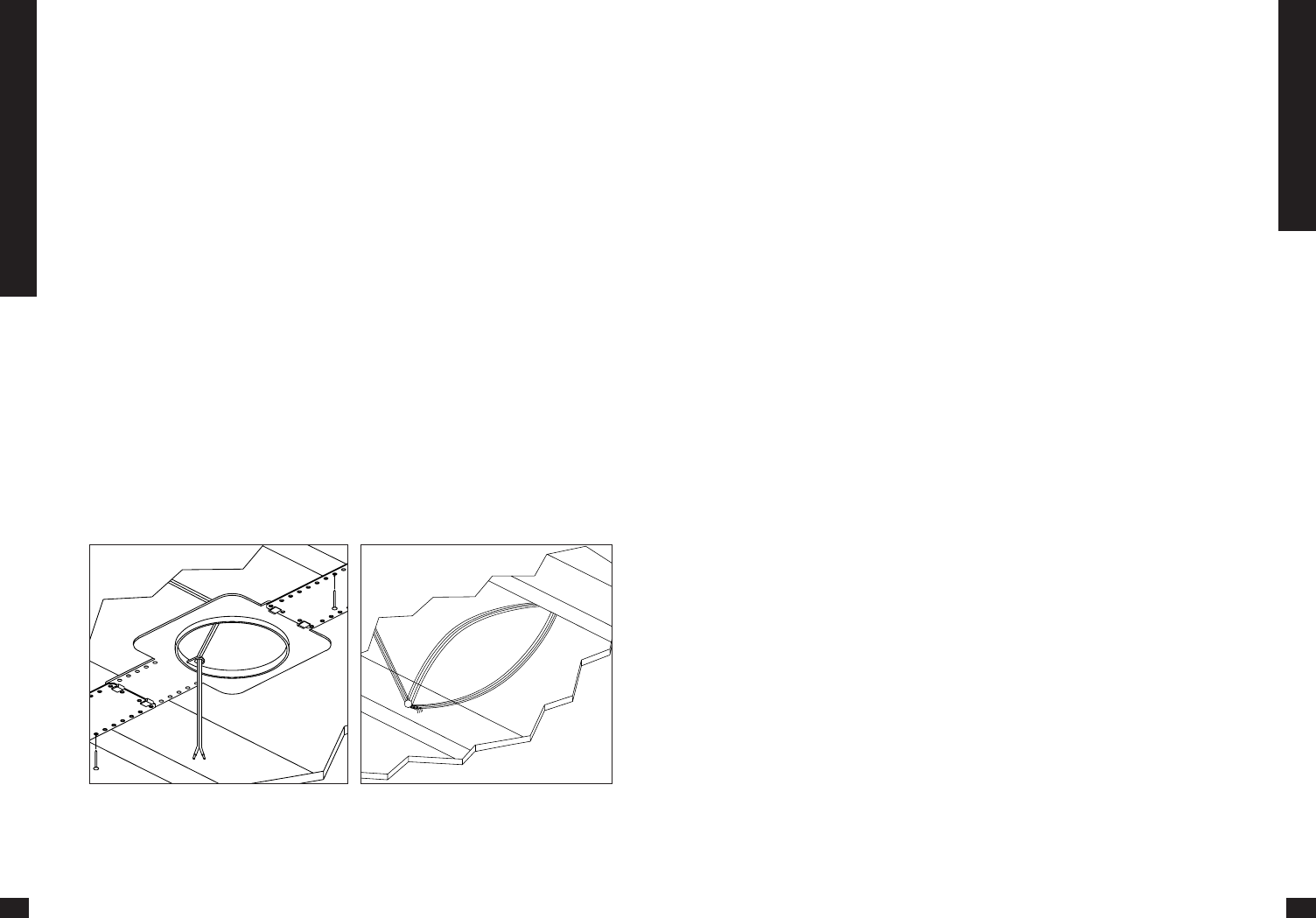
Concealing Speaker Wire for a
Future Installation
Attach the speaker wire in a loop between
the ceiling joists and carefully mark the
exact location of the wire on a set of
plans. Ask the general contractor to inform
the drywall installers that the speaker wire
loops are concealed for future installa-
tions. (SeeFigure13)
13
Installation in New Construction
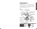
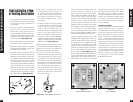
Figure 12 Figure 13
The optional hole saving brackets are installed
and the speaker wire is attached to the bracket.
The speaker wire is looped and hung on two
nail attached to the joists securing it for
future use. Make sure the location is noted
on house plans.