


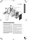
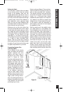

appreciate the tighter bass and extended
frequency response into the lower octaves
that the use of a backbox (or blocking off
the wall cavity) will provide. A hole cutting
template is provided with the AT8000
Series Bracket Kit. The cutout for the speak-
er must measure 9-3/4” x 17-1/4”.
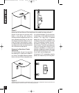
Insulating the Wall Cavity
When it is not possible to use a backbox,
good results can be achieved by treating
the interior of the drywall cavity with
Dynamat™ or a similar cabinet damping
material. At least two linear feet of damp-
ing material should be adhered to the rear
wall and to the front wall (one foot above
and one foot below the cutout) of the wall
cavity. Additionally, insulating the wall
cavity behind the speaker with fiberglass
insulation (e.g., R-19 unbatted insulation)
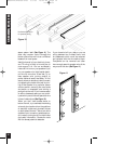
will improve performance. Try to keep the
amount of insulation used for each speak-
er equal, as bass output will be more con-
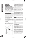
sistent. Further improvement can be made
by wedging a brace of 1x1 stock between
the front and rear walls, both above and
below the cutout. Use care when inserting
the brace, as too much pressure will create
a bulge in the wall.
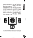
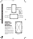
Speaker Placement
The AT8500 and AT8700 speakers feature
a low diffraction midrange/tweeter array
which employs Niles’ DSFG. This innova-
tive driver configuration can be adjusted to
provide optimum phase and frequency
response at the listening position. Please
read
Positioning the Midrange/Tweeter
Array
under Installation of the Speaker
and Grille in New or Existing Construction
on page 17 before deciding on a final
installation location for your AT8500 or
AT8700 speakers.
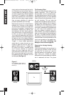
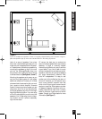
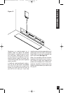
Placement for Critical Listening
If you like to imagine that the band or
orchestra is playing in front of you as you lis-
ten to music, or you are very conscious of
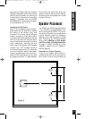
Speaker Placement
5
Speaker
Placement
Zone
Speaker
Placement
Zone
10’
5’
10’
Figure 2
DS00222A/AT8500-8700 3/1/99 10:48 AM Page 23