INTRODUCTION
Thank you for your purchase, and congratulations on
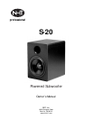
your selection of the NHT Pro S-20 powered subwoofer.
The S-20 will add dynamic bass response to any pair of
smaller, powered monitors, or can be used to reproduce
the .1 LFE channel for surround mixing. The S-20 was
designed to mate seamlessly with the NHT Pro M-00 and
M-20 monitor systems, and offers tremendous flexibility:
- Use multiple S-20’s to improve bass output if desired.
- Add an optional footswitch and you take the S-20 in and
out of the audio chain on the fly.
- Use as a ported or sealed design as NHT includes a
port plug with every S-20.
Investing some time learning about the S-20's features
and capabilities will reward you with the best possible
performance. Now would also be an excellent time to fill
out and send in your warranty registration card; or regis-
ter online in the Support section at www.nhtpro.com.
This action will automatically extend both the parts and
labor warranty for an additional two years, for a total of
three years! If at any time, you require assistance, call
our customer service hotline at (800)-NHT-9993 (648-
9993).
USER CONTROLS / CONNECTORS
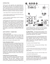
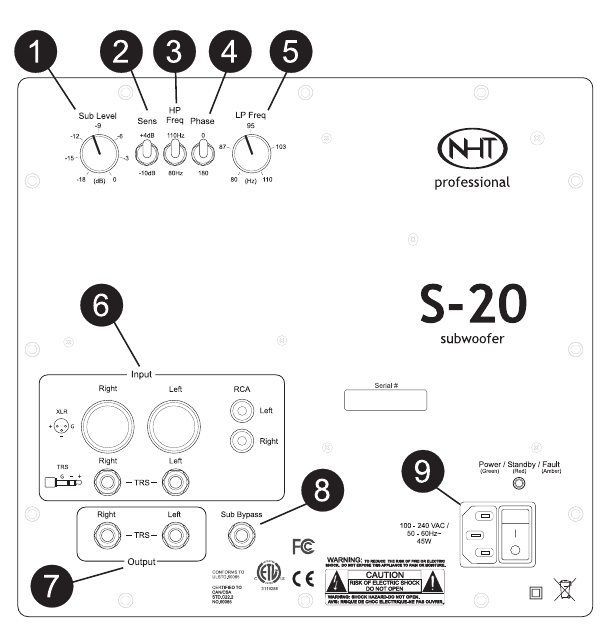
1) Sub Level Control:
The subwoofer level control matches the S-20 output
level to the satellite monitors. This control differs from
most as it doesn't turn the woofer all the way off, but
offers a 18dB range of adjustment. Fully clockwise, out-
put is maximum (0 dB or unity). In the counter clockwise
position, the sub output is attenuated by 18dB.
2) Input Sensitivity Control:
This control affects the level of all signals that go through
the S-20, both the subwoofer and satellite signals. Use
the +4dB position when you have a normal or high signal
level (most cases). Use the -10dB position when you
have a very low signal level (rarely). When setting up the
system, start with the control in the +4dB position. If the
system output is adequate, when your signal source has
it's volume or gain control at the maximum position, leave
the control in that position. If the system does not have
enough output, move the control to the -10dB position.
Following this procedure will give you the minimum sys-
tem noise level.
3) High Pass (HP) Frequency Switch:
The High Pass Frequency switch determines the lowest
frequency passed on to the satellite monitors. There are
two settings: 80Hz and 110Hz. Selecting the proper
switch position (see the Initial Control Settings section
on Pg. 4) will help blend the overall system response and
increase power handling. Setting the Subwoofer Bypass
switch to BYPASS eliminates this circuit and sends all
frequencies in the signal to the satellite monitors.
4) Phase Switch: This switch sets the polarity of the
subwoofer at either the 0° position (normal phase) or the
180° position (reverse phase) to achieve the smoothest
possible bass response in your system.
This phase-reversing option is important because when
bass frequencies come from both the subwoofer and the
main speakers, peaks and dips in the frequency
response can occur at the listening position. In these
cases, reversing the subwoofer polarity can improve
blending and balance.
To properly set the Subwoofer Phase:
• Play familiar music, reversing polarity settings. Listen
from your usual position.
• Avoid evaluating while standing above the subwoofer or
amplifier; sound at the listening position will be signifi-
cantly different.
• The correct setting is the one in which the bass is the
loudest at the listening position.
5) Low Pass (LP) Frequency Control:
This control allows fine adjustment of the subwoofer
crossover point to match the point where the satellites
roll off at the low end of their response. This detented low
pass control has a range of 80Hz -110Hz.
2


