


Installation: Existing Construction (retrofitting finished ceilings)
Warning: Exercise caution when drilling into existing ceilings. Do not drill through
existing wires, pipes, conduits, heating or air conditioning ducts. If you feel resis-
tance while drilling, stop immediately. Do not install the speaker into a drop ceiling or
soft ceiling, as this type of construction will not support its weight.
1. Using a studfinder or the “knocking” method, locate the joists in the ceiling area where you
wish to mount the speaker. The speaker will be mounted between adjacent joists, no closer
than two inches from either joist.
2. Determine that there are no obstructions above the desired cutout area. This may be
accomplished by drilling a hole in the center of the cutout area and using an “L”-shaped piece
of metal (like a coat hanger) to “feel around” above the ceiling. If you discover an obstruc-
tion, fill the hole with patching compound and try another location.
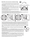
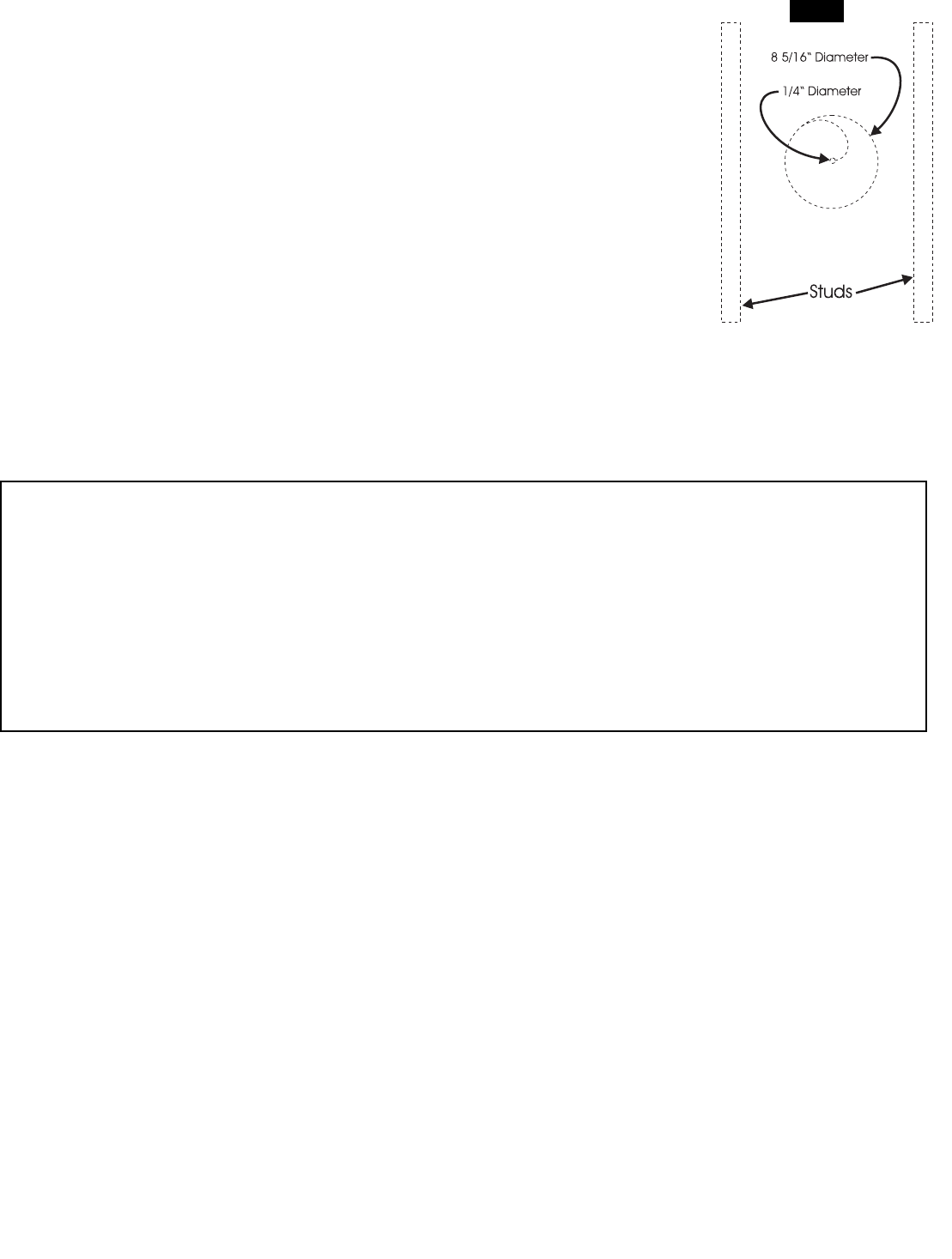
3. If there are no obstructions found above the ceiling, use the supplied cutout template and
a pencil to draw a 8-1/2” diameter outline of the area to be cut out. Begin by drilling a hole on the inside of the circle with
a 1/4” bit. Then cut out the ceiling section with a utility knife or keyhole saw, following the line traced around the cutout
template (fig.7). If the ceiling is painted, use the keyhole saw. Once installed, the bezel outer frame will extrude out about
1/2 inch beyond the perimeter of the cutout to hide minor imperfections in the cutout.
4. If the ceiling is constructed of lath and plaster, outline the penciled circle with masking tape, drill a 1/4” hole, and use a
utility knife to cut through the plaster down to the lath. Use a saber saw with a metal cutting blade or a pair of tin snips to
gently cut through the lath, being careful not to vibrate plaster off the ceiling.
5. To mount the CS-6.1 Ci or CS-6.3 Ci into an existing ceiling, the use of a mounting bracket is optional.
6. Connect the speaker cable to the spring clips (CS-6.1 Ci) or spring posts (CS-6.3 Ci) on the back of the bezel, making
sure to observe correct polarity (see “Connections”).
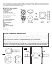
7. The bezel (with driver) mounts to the existing ceiling via four plastic mounting clamps on the back of the bezel that
swivel to “sandwich” the bezel in place between its protruding outer frame and the rear surface of the drywall. First rotate
the mounting clamps counterclockwise so that the body of the bezel can slide through the cutout in the ceiling. Exercise
caution not to damage the driver (fig 4).
8. Holding the bezel in one hand, rotate the mounting clamps via four Philips-head screws surrounding the driver on the
front of the bezel (fig 5). Tighten screws snugly, making sure not to over-tighten, as this may compromise the fit of the
bezel. The use of power screwdrivers is not recommended. The absorptive strips on the back the bezel frame reduce
unwanted vibrations against the drywall and will compress slightly to allow the bezel frame to rest flush against the ceiling.
9. If the bezel frame and grille are to be painted in the ceiling, install the paint shield to protect the driver from overspray
(see “Painting”). Once painting is complete, remove the paint shield and set it aside for use in Step #10.
10a. (CS-6.1 Ci only) The CS-6.1 Ci uses two absorptive foam pads on the inside of the grille to control sound radia-
tion (fig.6). There are two circular sections in the center of the paint shield that serve as templates for attaching them.
Punch out the larger circle, and the smaller circle from within it. Place the paint shield (minus the circular sections) on the
inside of the metal grille and attach the larger absorptive pad onto the grille through the circular cutout. Then attach the
smaller absorptive pad on top of the larger pad, using the larger cutout circle as a template. When attached correctly, the
two pads resemble a stepped cone.
10b. (CS-6.3 Ci only) The CS-6.3 Ci uses one absorptive foam pad on the inside of the grille to control sound radiation
(fig.6). There are two circular sections in the center of the paint shield that serve as templates for attaching it. Punch out
the larger circle (not the smaller circle within it). Place the paint shield (minus the circular section) on the inside of the metal
Tech Tips: Optimizing Sonic Performance
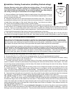
Bass response is smoothest when the speaker is mounted into a rigid ceiling that flexes very little. For improved per-
formance, add 2”x 4” cross-braces horizontally roughly one foot to either side of the speaker location. Use wood glue
and extra screws when attaching the drywall to the joists around the speaker. Additionally, once the speaker cutout has
been made in the drywall, add a strip of wood glue where the drywall meets the joists and cross-braces.
For more controlled bass response, add insulation to the ceiling cavity around and behind the speaker to provide
acoustic damping. Be sure to add the same amount of insulation to speakers in the same room to ensure consistent
sound. Use R-12 or R-19 fiberglass insulation, and be sure to wear protective gloves to avoid contact with the fibers. If
the insulation is paper- or foil-faced, position the paper or foil side away from the speaker. If the new or existing insula-
tion is the “loose” type, place a thin sheet of fiberglass over the top of the speaker to keep out small debris.
fig.7