


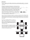
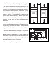
6. Insert the iW4 mounting bracket diagonally through the cutout in
the wall, then pull forward into position. If the cutout was cut cor-
rectly according to the cutout template, the bracket should fit snug-
ly into place. The plastic tabs on all sides of the bracket will rest
against the rear side of the wall (fig.10). If the tabs interfere with a
stud, break them off with pliers.
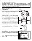
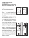
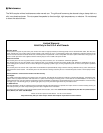
7. While holding the bracket flat against the rear side of the wall
with one hand, attach the bezel to the bracket with (8) 4 x 50mm
recessed head screws that line up with the 8 raised bosses on the
bracket (fig. 11). Tighten screws snugly, making sure not to over-
tighten, as this may compromise the fit of the bezel. The use of
power screwdrivers is not recommended. The absorptive strip on
the back of the bezel's outer frame reduces unwanted vibrations
against the drywall, and will compress slightly to allow the frame to
rest flush against the wall on all four sides. When installed correct-
ly, the bracket and bezel "sandwich" the drywall.
8. If the iW4 bezel frame and grille are to be painted in the wall,
paint now before installing the baffle (see "Painting" on the next
page).
9. Add a 26" long piece of unbacked R19 fiberglass insulation to
the enclosure. (Be sure to wear protective gloves and goggles
when handling fiberglass to avoid contact with the fiber). You may
need to cut a 11" wide by 7" high rectangular hole in the center of
the piece of fiberglass to make room for the crossover on the back
of the baffle.
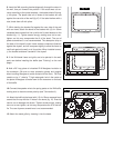
10. Connect the speaker wire to the spring posts on the iW4 baffle,
making sure to observe correct polarity (see "Connections").
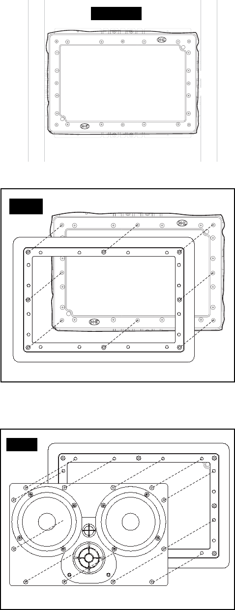
11. Attach the baffle to the bezel with (12) 4 x 20mm recessed head
screws that line up with the 12 holes in the bezel (fig. 12). Exercise
caution not to damage the drivers. Tighten screws snugly, making
sure not to over-tighten, as this may compromise the fit of the baf-
fle. The use of power screwdrivers is not recommended.
12. Attach the metal grille by inserting it into the bezel.
34
34
12
12
fig.12
1
1
34
34
12
12
fig.11
fig.10