


Installation: Existing Construction
(retrofitting finished ceilings)
Warning: Exercise caution when drilling into existing ceilings. Do not drill
through electrical wires, pipes, conduits, heating or air conditioning ducts. If you
feel resistance while drilling, stop immediately. Do not
install the speaker into a
drop ceiling or soft ceiling, as this type of construction will not support its weight.
1. Using a studfinder or the “knocking” method, locate the joist s in the ceiling area where
you wish to mount the speaker. The speaker will be mounted between adjacent joists,
no closer than two inches from either joist.
2. Determine that there are no obstructions above the desired cutout area. This may
be accomplished by drilling a hole in the center of the cutout area and using an “L”
shaped piece of metal (like a coat hanger) to “feel around” above the ceiling. If you dis-
cover an obstruction, fill the hole with patching compound and try another location.
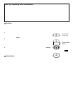
3. If there are no obstructions found above the ceiling, use the supplied cutout template
and a pencil to draw a 10” diameter outline of the area to be cut out. Begin by drilling a
hole on the inside of the circle with a 1/4” bit. Then cut out the ceiling section with a util-
ity knife or keyhole saw, following the line traced around the cutout template (fig.7). If
the ceiling is painted, use the keyhole saw. Once installed, the speaker assembly outer
frame will extend about 1/2 inch beyond the perimeter of the cutout to hide minor imper-
fections in the cutout.
4. If the ceiling is constructed of lath and plaster, outline the penciled circle with mask-
ing tape, drill a 1/4” hole, and use a utility knife to cut through the plaster down to the
lath. Use a saber saw with a metal cutting blade or a pair of tin snips to gently cut
through the lath, being careful not to vibrate plaster off the ceiling.
5. To mount the NHT in-ceiling speaker into an existing ceiling, the use of a mounting
bracket is optional.
6. Connect the speaker wire to the spring posts on the back of the bezel, making sure
to observe correct polarity (see “Connections”).
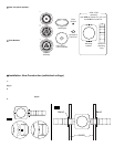
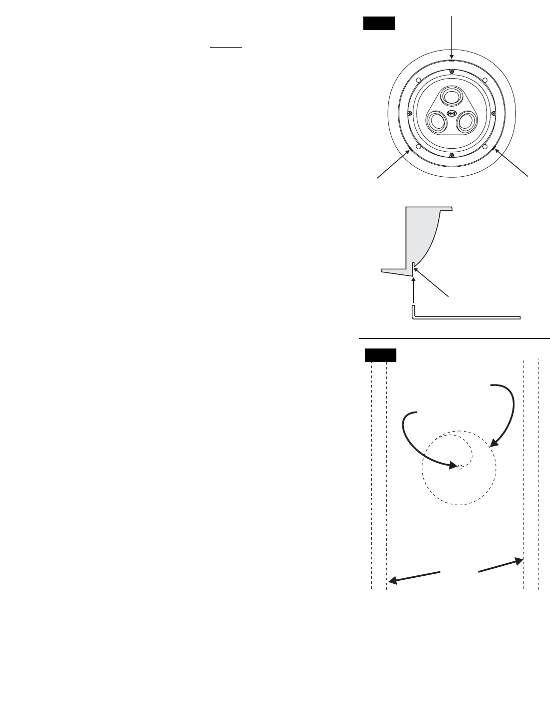
7. The speaker assembly mount s to the existing ceiling via four plastic mounting clamps
on the back of the speaker assembly that swivel to “sandwich” the speaker assembly in
place between its protruding outer frame and the rear surface of the drywall. First rot ate
the mounting clamps inward so that the body of the speaker assembly can slide through
the cutout in the ceiling. Exercise caution not to damage the driver (fig 4).
8. Tighten the screws snugly, making sure not to over tighten, as this may compromise
the fit of the speaker assembly. The use of power screwdrivers is not recommended.
The gasket on the back the speaker assembly lip reduces unwanted vibrations against
the drywall and will compress slightly to allow the speaker assembly lip to rest flush
against the ceiling.
9. If the bezel frame and grille are to be painted in the ceiling, install the paint shield to
protect the driver from overspray (see “Painting”). Once painting is complete, remove
the paint shield and set it aside for use in Step #10.
10 The NHT in-ceiling speakers use an absorptive foam pad (except the iC1) on the
inside of the grille to shape the sound radiation (fig.5). There is a circular section in the
center of the paint shield that serves as a template for attaching it. Punch out the per-
forated circle. Place the paint shield (minus the circular section) on the inside of the metal grille, remove the backer from the adhesive
dot and attach the larger absorptive pad onto the grille through the circular cutout.
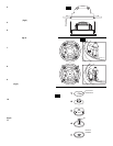
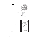
11. A strip of butyl rubber is provided with this product. Application of butyl rubber is not required, but can be used to provide a ddition-
al security when mounting the grill in place. Cut a 1/4” long piece of butyl rubber from the end of the roll provided. Peel off the paper
covering and roll the rubber between your fingers until it makes a small cylinder. Make three of these cylinders and place them in the
groove before installing the grill (fig.6).
12. Attach the metal grille by inserting it into the grooves in the speaker assembly.
Joists
Cutout Diameter
1/4“ Diameter
fig.7
Apply Here
fig.6