


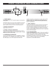
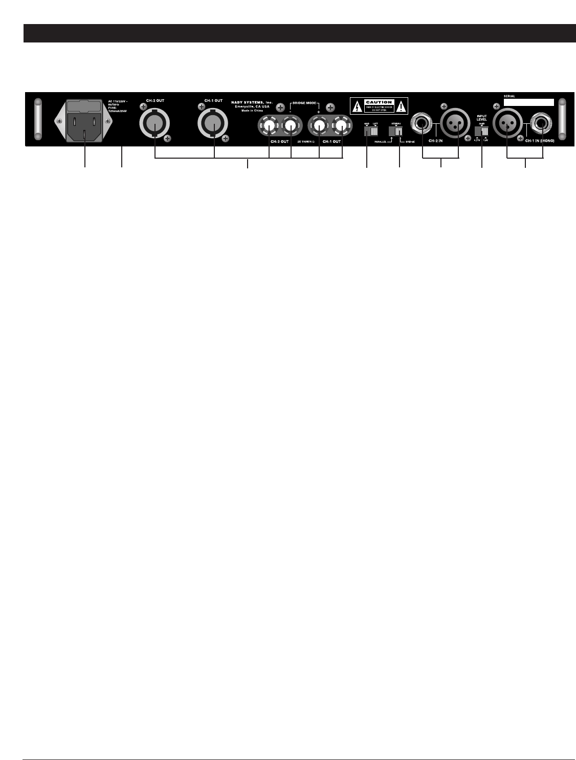
REAR CONTROLS AND CONNECTIONS
6
(12)
7. BALANCED INPUT CONNECTORS (1/4" TRS & XLR)
These 1/4" (6.3mm) TRS (Tip/Ring/Sleeve) phone jacks and XLR
jacks are compatible with balanced inputs and are wired as
Tip/Pin 3 = (-), Ring/Pin 2 = (+), and Sleeve/Pin 1 = Ground.
Input impedance is 14K Ohms.
Since the channel TRS phone jacks and XLR jacks are wired
internally in parallel, you can parallel this unit with another
amplifier by using either the LINE 1/4" jack or the XLR jack
(depending on which you’re using to input your signal) to output
the signal to the input jack of the other amplifier.
The 1/4" TRS phone jacks can also be used for unbalanced
inputs. For TRS phone plugs, simply connect the unused side of
the balanced input to ground. For 1/4" TS phone plugs, no
change is necessary for compatibility with this input. Balanced
input signals are recommended as they are less prone to AC
hum. For long cable runs a source of less than 600 ohms output
impedance is needed to avoid signal loss. For short cable runs
an unbalanced signal input should be suitable.
(Note: Do not use both unbalanced and balanced cables in the
same set-up as that can unbalance all the connections when
daisy-chaining, resulting in hum.)
For stereo (two-channel) operation, use the inputs for both
Channel 1 and Channel 2; for parallel or bridged mono operation,
use only Channel 1 input. (See 9. MODE SELECTOR
SWITCHES below for more explanation.)
8. INPUT LEVEL SWITCH
Sensitivity slide switch offers 3 sensitivity inputs of operation;
0.77 volts, 1.0 volts & 1.44 volts.
9. MODE SELECTOR SWITCH
The SPA Series amplifiers offer 3 modes of operation:
PARALLEL, STEREO & BRIDGED. Slide the switch to one of the
three positions for your application.
• PARALLEL (MONO) INPUT — This mode allows both
channel outputs to operate in parallel with the same signal. In
this mode, use channel 1 input and Level Control to operate
Channel 1 and Channel 2 Speaker Outputs. Channel 2 input
is not operational.
(11)
• STEREO INPUT — This is the most common mode
generally used, and allows independent control of 2 separate
signals such as stereo, main and monitor live mixes, and bi-
amp operation (highs in one channel and lows in the other).
• BRIDGED MONO — This mode combines the power of
both channels to drive a single speaker. Connect the input
signal to Channel 1 input for bridged mono operation. When
in Bridged mode, use the red binding post (banana jack)
outputs only. If Channel 1 and Channel 2 outputs are used,
the Speakers will be out of phase.
(CAUTION: This amplifier can deliver high power into a speaker.
Make sure that the speaker can handle the power output of this
amplifier)
10. GROUND LIFT SWITCH
Switch to disconnect the chassis from ground if necessary to
eliminate hum caused by ground loops.
11. SPEAKER OUTPUT CONNECTORS
Speakon™ and binding post (banana jack) outputs are
compatible with a speaker load of 4ohms or greater (8 ohms or
greater for bridged operation). Do not use less than an 8 Ohm
load when in Bridged mode. Connections are as depicted on the
rear panel.
12. FUSE HOLDER & POWER CORD CONNECTOR
This fuse holder contains an AC primary fuse. When this fuse
blows, replace it with the same type fuse, size and power rating
(see SPECIFICATIONS). If it continuously blows, stop replacing
the fuse and refer servicing to qualified personnel. The cord
connector is used to connect the AC power source to your power
amplifier.
(CAUTION: After checking the AC supply voltage, be sure that
the correct fuse is in the fuse holder.)
CAUTION: DO NOT REMOVE THE AC PLUG CENTER
GROUNDING PIN.
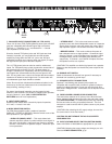
13. INPUT VOLTAGE SELECT SWITCH (BOTTOM PANEL)
Select 115V/60Hz or 230V/50Hz as appropriate for your area.
(CAUTION: Selecting the wrong voltage can damage your unit.
See also POWER CONNECTION, pg 6)
(10)
(9)
(7)
(8)
(7)
(13)
Bottom
Panel