


4
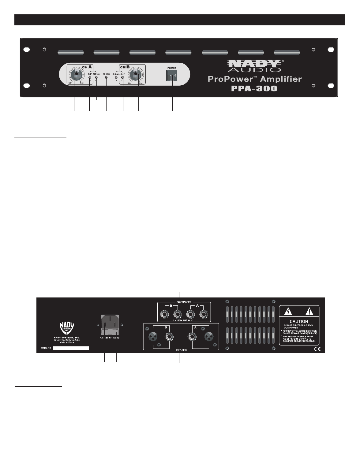
FRONT & REAR CONTROLS AND CONNECTIONS
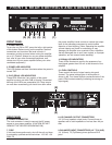
FRONT PANEL
1. POWER SWITCH
To turn the unit ON or OFF, press the left or right portion
of this button. Before turning on the amplifier, check all
connections and turn down the level controls. A
momentary muting is normal when turning the amplifier
on or off. (Caution: Always turn on your power amplifier
last, after all your other connected equipment, and
always turn off your power amplifier before your other
connected equipment.)
2. POWER LED INDICATOR
This LED flashes and then illuminates when the power is
turned “ON”.
3. CLIP (PEAK) LED INDICATORS
These LEDs illuminate if any section of the power
amplifier’s output are within 3dB of clipping. Occasional
blinking of the LEDs are acceptable, but if they remain
on more than occasionally you should turn down either
the power amplifier’s level controls or reduce the output
level of the preceding component to avoid audible
distortion or hard clipping. (Note: Operating the amplifier
at hard clipping can result in overheating or may
damage your amplifier over a period of time. Amplifiers
that are damaged due to such user neglect, or improper
operation, are not covered under warranty.)
4. SIGNAL LED INDICATORS
These LEDs illuminate to confirm the presence of an
input signal greater than 100 mV at that channel of the
amplifier
5. LEVEL CONTROLS
These control the level of signal coming into each
channel. The actual voltage gain of the amplifier is
shown in dB. Turn these controls counterclockwise if the
peak LEDs illuminate steadily (indicating too strong an
input signal).
(1)
(5)
(2) (5)(3)
(4)
(4)
(3)
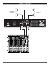
REAR PANEL
6. POWER CONNECTOR
The cord connector is used to connect the AC power
source to your power amplifier. (CAUTION: DO NOT
REMOVE THE CENTER GROUNDING PIN.)
7. FUSE
If this fuse blows continuously, shut off the unit and have
it serviced by qualified service technician. 115V AC ~6A
250V FB
8. L/R CHANNEL OUTPUT CONNECTORS
1/4” (6.3 mm) speaker output jacks. Connect these to
speakers with a total impedance of no less than 4Ω per
side.
9. BALANCED INPUT CONNECTORS (1/4" TS & XLR)
1/4" (6.3mm) TS (Tip/Sleeve) phone jacks and XLR
jacks.
(6)
(7)
(8)
(9)